Advertisement
Table of Contents
Advertisement
Table of Contents

Related Manuals for Flow Paser CF900


Summary of Contents for Flow Paser CF900
- Page 1 ® PASER CF900 ABRASIVE DELIVERY SYSTEM...
-
Page 2: Intended Use
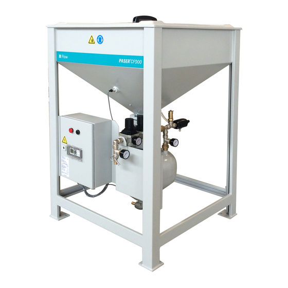
PASER CF900 Abrasive Delivery System Intended use The PASER CF900 Abrasive Delivery System (ADS) is designed for the continuous transport of abrasive materials. A programmable logic controller (PLC) constantly monitors the level of abrasive, and a control cabinet provides visual and audio feedback. -
Page 3: Personal Protective Equipment (Ppe)
Personnel must wear dust masks or respirators when loading abrasive materials into the silo to prevent particle or dust inhalation. Hearing protection is recommended. © 2016–2017 Flow International Corporation Page 3 of 31... -
Page 4: Safety Labels
WARNING indicates a hazardous situation, which if not avoided, could result in death or serious injury. CAUTION indicates a hazardous situation, which if not avoided, could CAUTION! result in minor or moderate injury. © 2016–2017 Flow International Corporation Page 4 of 31... - Page 5 1. Stop the ADS by turning off the power switch, and then lock and tag the power switch. 2. Turn off the air supply to the ADS, and then lock and tag the air source. © 2016–2017 Flow International Corporation Page 5 of 31...
-
Page 6: Specifications
Operating pressure/volume ..........5.5 bar (80 psi) @ 566 lpm (20 scfm) Surge pressure/volume ........5.5–6.5 bar (80–94 psi) @ 2250 lpm (80 scfm) Maximum compressed air volume ....dependent on abrasive material and flow rate Quality of compressed air ................ - Page 7 Sound level, depressurization ....................98 dBa Sound level, repressurization ..................... 79.4 dBa Transport the ADS Contact Flow Technical Service if you are connecting the ADS to a different voltage power supply in the new location. CAUTION! Comply with your local regulations for moving equipment. Flow recommends the presence of flaggers and spotters.
- Page 8 Vessel low abrasive switch. When this switch does not sense abrasive, it signals the PLC to start the continuous warning indicator and continuous audio signal. The display panel shows the “Vessel Empty” message. If you are using FlowCUT™, the program stops. © 2016–2017 Flow International Corporation Page 8 of 31...
-
Page 9: Control Cabinet
The PLC constantly monitors the operating conditions and sends control signals to the solenoid valves, the warning indicator, and the audio signal. Number Description Electrical hazard warning label Yellow warning indicator Audio signal Display panel CE label Panel lock © 2016–2017 Flow International Corporation Page 9 of 31... - Page 10 You can accept the selected signal in the ADS and use it there for an additional alarm or as a way to stop the cutting process. © 2016–2017 Flow International Corporation Page 10 of 31...
- Page 11 20 FlowCUT again after the continuously. seconds. warning indicators have The ADS is stopped. It turned off. starts after the vessel fills with abrasive. © 2016–2017 Flow International Corporation Page 11 of 31...
-
Page 12: Pneumatic Controls
Main System Relief— Air Supply Valve Control— Factory set to 7 bar (100 SOL311 Normally Closed psi) Gauge 1 Exhaust 1 Gauge 2 Exhaust 2 Gauge 3 Exhaust 3 Gauge 4 Exhaust 4 © 2016–2017 Flow International Corporation Page 12 of 31... - Page 13 PR1 to 5.5 bar (80 psi) and PR2 to 2.8 bar (40 psi). If the minimum difference is maintained, you can adjust PR1 and PR2 to control the abrasive flow. Proximity switch PS219 sends a signal to the PLC to indicate presence of abrasive. If there is no abrasive, the PLC sends a signal to release the pressure from the vessel, and then sends a signal to open the pinch valve.
-
Page 14: Normal Operation
Pressure Switch When engaged, the pressure When disengaged, FlowCUT (Mach 4c only) switch signals FlowCUT that the prevents any programs from vessel has air pressure. starting and stops any running programs. © 2016–2017 Flow International Corporation Page 14 of 31... - Page 15 Observe proper lifting techniques when lifting abrasive bags. Avoid adding abrasive near the pressure valve muffler (below). 2. Put the lid on the silo. © 2016–2017 Flow International Corporation Page 15 of 31...
- Page 16 4. Ensure that the PR1 gauge is at 5.5 bar (80 psi) and PR2 is at 2.8 bar (40 psi). 5. Turn on the power switch. Shutdown Turn off the power switch. © 2016–2017 Flow International Corporation Page 16 of 31...
-
Page 17: Maintenance
2. Remove abrasive until it is below the silo low abrasive switch. 3. Open the control panel, and then disconnect the cables from TB1-9, TB1-10, and TB1-11. © 2016–2017 Flow International Corporation Page 17 of 31... - Page 18 7. Install the new proximity switch. Turn the switch so that access to the adjustment screw is easy. Tighten the locknut to hold the switch in position. © 2016–2017 Flow International Corporation Page 18 of 31...
- Page 19 WARNING! Failure to do the lockout tagout procedure can result in equipment damage or injury to personnel. 3. Open the control panel, and then disconnect the cables from TB1-6, TB1-7, and TB1-8. © 2016–2017 Flow International Corporation Page 19 of 31...
- Page 20 7. Install the new switch. Turn the switch for easy access to the adjustment screw. Tighten the locknut to hold the switch in position. © 2016–2017 Flow International Corporation Page 20 of 31...
- Page 21 Replace the PV1 pinch valve seal after approximately 6000 switching cycles. An assistant is required during some steps of this procedure. PARTS Pinch valve seal (hose insert) TOOLS 6 in. adjustable wrench 12 in. adjustable wrench SUPPLIES Lint-free rags Wooden blocking © 2016–2017 Flow International Corporation Page 21 of 31...
- Page 22 6. Disconnect the cables from the manifold pressure sensors. Label the cables. This helps to connect the cables later. 7. Remove the two bolts that attach the tubing support to the sheet metal. © 2016–2017 Flow International Corporation Page 22 of 31...
- Page 23 9. Disconnect the cable from the solenoid mounted on the pinch valve. 10. Position wooden blocking between the floor and the abrasive outlet port to support the vessel during removal. CAUTION! The vessel weighs over 90.7 Kg (200 lb) when full. © 2016–2017 Flow International Corporation Page 23 of 31...
- Page 24 13. Remove the gasket from between the vessel and the pinch valve housing. Clean the gasket with a lint-free rag, and then set gasket aside. 14. Remove the M16 hex screws and nuts, and then remove the pinch valve. © 2016–2017 Flow International Corporation Page 24 of 31...
- Page 25 Replace the pinch valve if the tapered surfaces have damage. 19. Clean the tapered surfaces with a lint-free rag. The surfaces must be clean before installing the new pinch valve seal. © 2016–2017 Flow International Corporation Page 25 of 31...
- Page 26 M16 screws and nuts. The gap between the silo flange and the upper pinch valve flange must be even after all of the screws are tight. © 2016–2017 Flow International Corporation Page 26 of 31...
- Page 27 38. If PR1 and PR2 were set to pressures different from what is specified on the regulator labels, set PR1 and PR2 to their previous settings. 39. Fill the silo with abrasive. 40. Remove the lockout from the power switch. © 2016–2017 Flow International Corporation Page 27 of 31...
-
Page 28: Engineering Drawings
Engineering drawings Schematics Part number Revision Electrical 86200038 © 2016–2017 Flow International Corporation Page 28 of 31... -
Page 29: Troubleshooting
2 bar (30 psi) below the supply pressure. The pinch valve seal in PV1 Replace the pinch valve seal. is defective © 2016–2017 Flow International Corporation Page 29 of 31... - Page 30 Examine for restrictions in the hose between the vessel and the cutting system. Examine for restrictions in the abrasive metering system of the cutting system. © 2016–2017 Flow International Corporation Page 30 of 31...
-
Page 31: Spare Parts
Dual stage hopper, 200 Liter 86700022 Dual stage hopper, 26 Liter (vessel) 86700016 Leveling pad 86700018 Pinch valve 86700041 Coupling, Hex, brass, 3/4pt 86200023 Switch, proximity (used in storage container and vessel) © 2016–2017 Flow International Corporation Page 31 of 31...
Need help?
Do you have a question about the Paser CF900 and is the answer not in the manual?
Questions and answers