Table of Contents
Advertisement
Quick Links
MICROPROCESSOR BASED
DIGITAL ELECTRONIC
INDICATOR
OPERATING INSTRUCTIONS
12/01 - Code: ISTR_M_TLI40_E_03_--
ASCON TECNOLOGIC S.r.l.
Viale Indipendenza 56
27029 Vigevano (PV) ITALY
TEL.: +39 0381 69871 - FAX: +39 0381 698730
http:\\www.ascontecnologic.com
e-mail: info@ascontecnologic.com
FOREWORD
This manual contains the information necessary for the product to
be installed correctly and also instructions for its maintenance and
use; we therefore recommend that the utmost attention is paid to the
following instructions.
Though this manual has been issued with the greatest care, ASCON
TECNOLOGIC will not take any responsibility deriving from its use.
The same applies to each person or Company involved in the
issuing of this manual.
This document is the exclusive property of ASCON TECNOLOGIC
which forbids any reproduction and divulgation , even in part, of the
document, unless expressly authorized.
ASCON TECNOLOGIC reserves the right to make any formal or
functional changes at any moment and without any notice.
TLI40
ASCON TECNOLOGIC - TLI 40 - OPERATING INSTRUCTIONS - PAG. 1
INDEX
1
INSTRUMENT DESCRIPTION
1.1
GENERAL DESCRIPTION
1.2
FRONT PANEL DESCRIPTION
2
PROGRAMMING
2.1
PARAMETER PROGRAMMING
2.2
PARAMETER PROGRAMMING LEVELS
2.3
FAST PROGRAMMING OF ALARM THRESHOLDS
3
INFORMATION ON INSTALLATION AND USE
3.1
PERMITTED USE
3.2
MECHANICAL MOUNTING
3.3
ELECTRICAL CONNECTIONS
3.4
ELECTRICAL WIRING DIAGRAM
4
FUNCTIONS
4.1
MEASURING AND VISUALIZATION
4.2
PEAK VALUES MEMORIZATION AND HOLD FUNCTION
4.3
OUTPUTS CONFIGURATION
4.4
ALARM FUNCTIONS
4.4.1 ALARM OUTPUT CONFIGURATION
4.4.2 ALARM HYSTERESIS
4.5
FUNCTION OF KEY "U"
4.6
DIGITAL INPUT
4.7
RS 485 SERIAL INTERFACE
4.8
PARAMETERS CONFIGURATION BY A01
5
PROGRAMMABLE PARAMETERS
5.1
PARAMETERS TABLE
5.2
PARAMETERS DESCRIPTION
6
PROBLEMS , MAINTENANCE AND GUARANTEE
6.1
ERROR SIGNALLING
6.2
CLEANING
6.3
GUARANTEE AND REPAIRS
7
TECHNICAL DATA
7.1
ELECTRICAL DATA
7.2
MECHANICAL DATA
7.3
MECHANICAL DIMENSIONS, PANEL CUT- OUT AND
MOUNTING
7.4
FUNCTIONAL DATA
7.5
MEASUREMENT RANGE TABLE
7.6
INSTRUMENT ORDERING CODE
1 - INSTRUMENT DESCRIPTION
1.1 - GENERAL DESCRIPTION
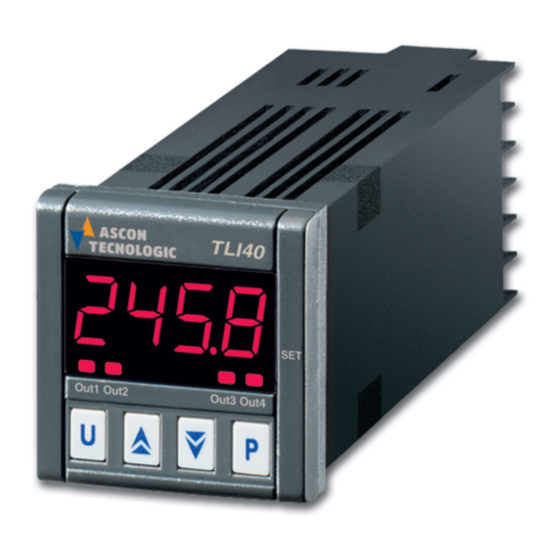
TLI 40 is a digital microprocessor-based indicator.
The input is programmable and accepts:
Temperature probes
- Thermocouples J,K,S,B,C,E,L,N,R,T
- Thermo-resistances PT100,
- Thermistors PTC and NTC
- Infrared sensors mod. ASCON TECNOLOGIC IRS
Normalized analogue signals
- 0/4..20 mA, 0/1..5 V, 0/2..10 V, 0..50/60 mV, 12..60 mV
Potentiometer
- with resistance > 1 KΩ
The instrument can have up to 4 alarm outputs : relay type or can
drive solid state relays type (SSR).
One of this output can be analogue type (0/4..20 mA o 0/2..10 V)
and used as measurement retransmission output.
The instrument can be equipped with a programmable digital input
as an alternative to output OUT4.
Furthermore, the instrument allows for RS485 serial communication
using MODBUS-RTU communication protocol and a transmission
speed up to 38.400 baud.
The process value is visualized on 4 red displays, while the output
status is indicated by 4 LED displays.
Other important available functions are: maximum end minimum
peak memory, Hold function, zero calibration (resetting) function
and/or
auto-ranging
for
sampling rate (from 8 to 64 sampl./sec.), parameters protection on
different levels.
potentiometer
input,
programmable
Advertisement
Table of Contents

Related Manuals for Ascon tecnologic TLI40


Summary of Contents for Ascon tecnologic TLI40
- Page 1 ASCON TECNOLOGIC reserves the right to make any formal or sampling rate (from 8 to 64 sampl./sec.), parameters protection on functional changes at any moment and without any notice. different levels. ASCON TECNOLOGIC - TLI 40 - OPERATING INSTRUCTIONS - PAG. 1...
-
Page 2: Front Panel Description
“P” is pressed, the display will decreases rapidly and, after two seconds in the same condition, the changing speed increases in order to allow the desired value to be reached rapidly. ASCON TECNOLOGIC - TLI 40 - OPERATING INSTRUCTIONS - PAG. 2... - Page 3 - for thermocouples J (J), K (CrAL), S (S), B (b), C (C), E (E), L (L), The instrument can be removed from its housing from the front side N (n), R (r), T (t) or for infrared sensors serie ASCON TECNOLOGIC : it is recommended that the instrument be disconnected from the power supply when it is necessary to carry out this operation.
-
Page 4: Output Configuration
U key that has been suitably “OALn”. programmed (see par. U key with function "USrb" = r.Pic) or The alarm functioning is instead defined by parameters : "ALnt " – ALARM TYPE ASCON TECNOLOGIC - TLI 40 - OPERATING INSTRUCTIONS - PAG. 4... - Page 5 With the hold function turned on, the instrument +0 = ALARM NOT DELAYED: The alarm is immediately activated carries out control according to the memorised measurement. when the alarm condition occurs. ASCON TECNOLOGIC - TLI 40 - OPERATING INSTRUCTIONS - PAG. 5...
-
Page 6: Digital Input
For additional info, please have a look at the A01 instruction program all the instrument’s configuration parameters. The software manual. protocol adopted for TLI40 is a MODBUS RTU type, widely used in ASCON TECNOLOGIC - TLI 40 - OPERATING INSTRUCTIONS - PAG. 6... -
Page 7: Programmable Parameters
46 HAL3 Alarm AL3 hysteresis OFF ÷ 9999 Group “O3” (parameters relative to output 3) 47 AL3d Activation delay of OFF ÷ 9999 Par. Description Range Def. Note alarm AL3 sec. ASCON TECNOLOGIC - TLI 40 - OPERATING INSTRUCTIONS - PAG. 7... -
Page 8: Parameters Description
By opening the contact, the - thermoresistances/thermistors (“HCFG”=rtd): Pt100 IEC (Pt1) or instrument starts normal measurement acquisition once more. thermistors PTC KTY81-121 (Ptc) or NTC 103AT-2 (ntc) ASCON TECNOLOGIC - TLI 40 - OPERATING INSTRUCTIONS - PAG. 8... - Page 9 0 and 15. The number to be programmed, that corresponds to the desired function, is alarm AL3. obtained adding the values reported in the following description : ASCON TECNOLOGIC - TLI 40 - OPERATING INSTRUCTIONS - PAG. 9...
- Page 10 "P1" alternatively to the value of the first point of setting. Now, please position the potentiometer in the first point of setting and program the value desired for that point using the UP and DOWN ASCON TECNOLOGIC - TLI 40 - OPERATING INSTRUCTIONS - PAG. 10...
- Page 11 Storage temperature: -10 ... +60 ° C “HCFG” = tc - 256 ... 1832 ° F -199.9 ... 999.9 ° F “SEnS” = J 7.3 – MECHANICAL DIMENSIONS, PANEL CUT-OUT AND MOUNTING [mm] ASCON TECNOLOGIC - TLI 40 - OPERATING INSTRUCTIONS - PAG. 11...
- Page 12 -19.99 ... 99.99 “SEnS” = 0.10 -1.999 ... 9.999 2 ... 10 V -199.9 ... 999.9 “HCFG” = UoLt -1999 ... 9999 -19.99 ... 99.99 “SEnS” = 2.10 -1.999 ... 9.999 ASCON TECNOLOGIC - TLI 40 - OPERATING INSTRUCTIONS - PAG. 12...
Need help?
Do you have a question about the TLI40 and is the answer not in the manual?
Questions and answers