Advertisement
SPECIFICATIONS
Power source
Charging time
Weight
Supplied accessories
CONTENTS
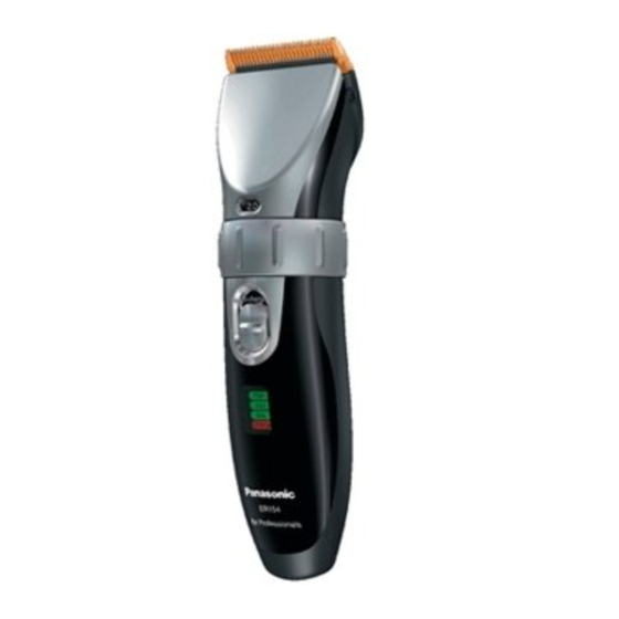
AC/Rechargeable Hair Clipper for Professional
AC/Rechargeable
AC 230V, 50Hz
1 hour
200g
Comb attachment (3mm/4mm, 6mm/9mm, 12mm/15mm)
Charging stand
Charging stand tray
Oil
Cleaning brush
Page
2
2
3
5
ER154-E8
© 2005 Matsushita Electric Works, Ltd. All rights
reserved. Unauthorized copying and distribution is a
violation of law.
ORDER NO. SD0512E51CE8
Page
7
8
8
Advertisement
Table of Contents

Subscribe to Our Youtube Channel
Related Manuals for Panasonic ER154-E8


Summary of Contents for Panasonic ER154-E8
-
Page 1: Table Of Contents
ORDER NO. SD0512E51CE8 AC/Rechargeable Hair Clipper for Professional ER154-E8 SPECIFICATIONS Power source AC/Rechargeable AC 230V, 50Hz Charging time 1 hour Weight 200g Supplied accessories Comb attachment (3mm/4mm, 6mm/9mm, 12mm/15mm) Charging stand Charging stand tray Cleaning brush CONTENTS Page Page 1 SCHEMATIC DIAGRAM... -
Page 2: Schematic Diagram
ER154-E8 1 SCHEMATIC DIAGRAM 2 WIRING CONNECTION DIAGRAM... -
Page 3: Disassembly Instructions
Follow the procedure below to disassemble the main body. 1. Remove the attachment. 2. First, hold the handle of the hair clipper firmly with the "Panasonic" name facing upward and set the dial to "2.0mm", and push the upper part of the blade away from the housing. - Page 4 ER154-E8 7. Loosen a screw and take out the name plate slightly inserting the slotted-head screwdriver to unhook the side. 8. Separate housing A and B.
-
Page 5: Assembly Instructions
ER154-E8 4 ASSEMBLY INSTRUCTIONS NOTE: Always set the dial to "2.0mm" when removing or attaching the blade; otherwise the blade can not be attached. Always set the dial to "0.8mm" when removing or attaching the comb attachment. 1. Set the click button and the dial spring to the housing A. - Page 6 ER154-E8 4. Insert the motor facing the sticker on the housing B side. NOTE: The motor has a own direction. Make sure to set the proper direction when reassembling. NOTE: Be certain that the lead wires are mounted in the proper position without setting over the housing ribs.
-
Page 7: Troubleshooting Guide
ER154-E8 5 TROUBLESHOOTING GUIDE (Refer to WIRING CONNECTION DIAGRAM) -
Page 8: Exploded View
ER154-E8 6 EXPLODED VIEW 7 REPLACEMENT PARTS LIST Ref. No. Part No. Part Name & Description Remarks Per Unit WER9792Y BLADE BLOCK WER151L9207 TAPPING SCREW K2.6-8 WER154L0168 SPRING FOR CUTTER WER154S3968 FRONT PANEL WER154S3288 ADJUSTING DIAL WER150L0137 DUST-PROOF RUBBER WER154K3058...
Need help?
Do you have a question about the ER154-E8 and is the answer not in the manual?
Questions and answers