Table of Contents
Advertisement
Quick Links
1656 Auto-Line Option
1656 Auto-Line Option
STS Instruments
OWNERS' MANUAL
STS Instruments
17711 Mitchell North
Irvine, CA 92614
United States of America
Phone Toll Free: 1-800-421-1921 (US and Canada only)
Phone: 1-580-223-4773
Fax: 1-580-226-5757
Email:
info@stsinstruments.com
Web:
www.stsinstruments.com
Owners' Manual
Page 1 of 32
Advertisement
Table of Contents

Related Manuals for STS 1656


Summary of Contents for STS 1656
- Page 1 1656 Auto-Line Option Owners’ Manual OWNERS’ MANUAL 1656 Auto-Line Option STS Instruments 17711 Mitchell North Irvine, CA 92614 United States of America Phone Toll Free: 1-800-421-1921 (US and Canada only) Phone: 1-580-223-4773 Fax: 1-580-226-5757 Email: info@stsinstruments.com Web: www.stsinstruments.com...
- Page 2 Rev: AB Date of Publication: May 2016 ©2015, All Rights Reserved STS Instruments. THE INFORMATION CONTAINED IN THIS MANUAL IS PROPRIETARY TO STS INSTRUMENS AND MAY NOT BE COPIED OR REPRINTED WITHOUT ITS EXPRESSED WRITTEN CONSENT. STS Instruments Page 2 of 32...
- Page 3 This warranty does not cover batteries or accessories not of STS Instruments manufacture. Parts used must be parts that are recommended by STS Instruments as an acceptable specified part. Use of non- authorized parts in the repair of this instrument will void the warranty.
-
Page 4: Table Of Contents
1656 Auto-Line Option Owners’ Manual Contents Introduction ................................7 Manuals ..................................7 Background ..................................7 Technical Specifications ............................8 Outputs ..................................8 Inputs..................................... 8 AC Input ..................................8 2.3.1 PLC Connector Pins .............................. 9 Environmental ................................9 Mechanical .................................. 10 Regulatory Compliance.............................. - Page 5 Table 2-1: PLC Connector Pin-out ..........................9 Table of Figures Figure 2-1: 1656 Auto-Line Front Panel – Shown with detachable handles/rack ears ..........10 Figure 2-2: 1656 Auto-Line Rear Panel – Shown without rack ears ................10 Figure 3-1: Auto-Line Option Connections to STS 1656 Tester ................... 15 Figure 4-1: Auto-Line Option Block Diagram .......................
- Page 6 1656 Auto-Line Option Owners’ Manual CAUTION READ Section 3, Installation and Safety Section 5, Operation Section 8, Maintenance of this manual before installing or operating this equipment. WARNING IF THIS EQUIPMENT IS NOT INSTALLED AND/OR USED IN A MANNER SPECIFIED...
-
Page 7: Introduction
For over 30 years, the STS Instruments Battery Element Testers have been the de-facto benchmark for Battery Cell quality testing. The new 1656 model builds on this legacy of reliable, high volume testing using a state-of-the-art digital design made possible by advanced microcontrollers (MCUs) and high resolution, fast Analog to Digital conversion (ADC) of voltage and current test signals. -
Page 8: Technical Specifications
1656 Auto-Line Option Owners’ Manual Technical Specifications This section includes performance specifications for the 1656 Battery Element Tester. All specifications are valid over the stated temperature. Calibration is performed at 23°C ± 5°. 2.1 Outputs Parameter Specification Notes High Voltage Channels... -
Page 9: Plc Connector Pins
1656 Auto-Line Option Owners’ Manual Parameter Specification Notes On/Off Switch Type Rocker Type, Front Panel. Press O to turn Off Line Cord Type IEC 60329, C13, Detachable AC Input Connector Type IEC 60320, C14 2.3.1 PLC Connector Pins Direction Signal... -
Page 10: Mechanical
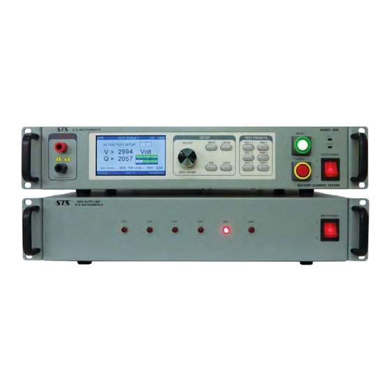
1656 Auto-Line Option Owners’ Manual 2.5 Mechanical Figure 2-1: 1656 Auto-Line Front Panel – Shown with detachable handles/rack ears Figure 2-2: 1656 Auto-Line Rear Panel – Shown without rack ears Parameter Specification Notes Dimensions 19” / 483 mm Incl. rack ears Width 16.7”... -
Page 11: Regulatory Compliance
Specification Notes CE Mark IEC61326-1:2013 Safety IEC61010-1:2010 2.7 Included Accessories Accessories listed are included with each 1656 Auto-Line unit as part of the ship-kit. Additional quantities may be purchases separately through customer service. Part Number Description Qty. Length 201746-AA HV Cabling from 1656 RPC to Auto-line chassis – Red 201747-AA HV Cabling from 1656 RPC to Auto-line chassis –... -
Page 12: Installation And Safety
If damage is evident, keep the original carton and file an insurance claim with the carrier. Check all content of the 1656 Auto-Line shipping carton to make sure you have received all items that make up the product. The table below lists the included items. -
Page 13: Operator Training
1656 Auto-Line Option Owners’ Manual Part Number Description Notes /Quantity 201770-AB 1656 Owners’ Manual, PDF format Available on line Certificate of Conformance Calibration Certificate 3.1 Operator Training One of the more important ways to promote safety is through operator training. Benefits of training are twofold. -
Page 14: Important Safety Precautions
1656 Auto-Line Option Owners’ Manual 3.3 Important Safety Precautions CAUTION ALWAYS FOLLOW RECOMMENDED SAFETY PRACTIVES WHEN OPERATING THIS EQUIPMENT After the equipment has been installed, a careful study should be made of the test station to determine what, if any, safeguards are needed. It is suggested that any electrical test station involving voltages in excess of 42.4 volts peak (approximately 30 volts RMS) should be equipped... -
Page 15: Connecting The Auto-Line Unit
Auto-Line unit, contact STS Instruments customer service to purchase longer wires. In general however, the distances between the Auto-Line test unit and the test fixture should be kept as short as possible. -
Page 16: Initial Setup Procedure
3.5 Initial Setup Procedure Proceed as follows: 1. Insert the AC line cord into a suitable AC outlet. The 1656 Auto-Line has a universal input and will operate from any voltage between 100Vac RMS L-N and 240Vac RMS L-N. 2. The included ground wire (Green/Yellow color) may be used to ground the Auto-Line chassis to a cabinet or other instrument if needed. -
Page 17: Theory Of Operation
The Auto-Line unit acts as a six channel high voltage path multiplexer controller by the main 1656 tester through the PLC interface. The Auto-Line option allows the test voltage to be applied to up to six separate channels (CH1 through CH6). Each channel is fully isolated from all other channels. -
Page 18: Operation
5.1 Controls, Indicators and Connectors Figure 5-1: 1656 Auto-Line Front Panel View Controls on the 1656 Auto-Line are limited to the power On/Off switch which also doubles as a power on indicator. There are six LED indicators on the 1656 Auto-Line units’ front panel. These indicators show which channel is selected, if any. -
Page 19: Menu Operation Information
Owners’ Manual 5.3 Menu Operation Information This section only covers use of the 1656 Auto-Line option from the 1656 tester’s front panel. It is assumed that the user is familiar with the 1656 Operator Manual and/or 1656 Owner’s Manual which are both supplied with the 1656 Battery Element Tester. - Page 20 1656 Auto-Line Option Owners’ Manual TEST SETUP <n> MENU Entry Type Description TEST VOLTAGE Parameter Sets the test voltage level for the selected test setup. For most battery types, a test voltage between 1500 V and 2000 V should be sufficient. Setting the test voltage too low may not allow possible defects to be found.
- Page 21 1656 Auto-Line Option Owners’ Manual TEST SETUP <n> MENU Entry Type Description Q METER List Opens the learn mode screen which allows the user to test multiple batteries by running repeated tests on a given battery while observing the Q read back value.
-
Page 22: Auto-Line Test Result Data Display
1656 Auto-Line Option Owners’ Manual 5.5 Auto-Line Test Result Data Display With the Auto-Line test option connected, the result display shows results for up to six battery elements. This is shown in the lower right corner of the display as can be seen in the figure below. -
Page 23: Utilities Menu - Auto-Line Enable
This menu may be used to enable or disable the Auto-Line option. Note: To use the Auto-Line option, the PLC interface must be installed in the 1656 Tester. If not, the Auto-Line ON/OFF selection field will not be visible. This is shown in the screen below. The presence of the PLC is indicated by scrolling through the INTERFACE SELECT choices. - Page 24 Description INTERFACE SELECTION List Selects between available digital remote control interfaces. The Model 1656 offers interfaces such as USB, RS232, RS485 or PLC. INTERFACE SETUP Allows parameter settings for the RS485 serial interface address of the unit (Range = 1~128).
-
Page 25: Application Notes
1656 Auto-Line Option Owners’ Manual Application Notes This section contains remarks and comments on practical matters that apply to testing battery elements using high voltage testers like the 1656. STS Instruments Page 25 of 32... -
Page 26: Maintenance
Check line receptacle for ground integrity. 7.3 Annual Maintenance There is no calibration requirement for the 1656 Auto-Line option. Individual fuses are used to protect the different sections of the equipment. Failure of any of the fuses is evidence either of fuse aging, abnormal line surges, or trouble in the unit. -
Page 27: Test Probes
Replacement test probes assemblies and fuses can be obtained by ordering the following: Part Number Description Notes 201758 Chassis Ground Cable, 1m/3.3’, Green/Yellow HV Cabling from 1656 RPC to Auto-line chassis, 1m/3.3’ – 201746-AA HV Cabling from 1656 RPC to Auto-line chassis, 1m/3.3’ – 201747-AA Black 201901 HV Wire Kit, terminated one end only, 3m/9.8’... -
Page 28: Service
Transportation costs for the return of the instrument to STS Instruments must be prepaid by the customer. Tester sent for repair should be shipped prepaid and insured to the address show below. -
Page 29: Ce Mark Declaration Of Conformity
1656 Auto-Line Option Owners’ Manual CE MARK Declaration of Conformity The manufacturer hereby declares that the product Product Name: STS Model 1656 Auto-Line Option Description: BATTERY ELEMENT TESTER Conforms to the following stands or other normative documents: RoHS (DIRECTIVE 2011/65/EU) -
Page 30: Index
1656 Auto-Line Option Owners’ Manual Index AC Input ............. 8 Mechanical............10 Accessories ............11 probes .............. 27 Application Notes ..........25 quality ............7, 13 CE Mark ............11 rear panel ............18 China ..............28 Regulatory Compliance ........11 controls ............ - Page 31 1656 Auto-Line Option Owners’ Manual STS Instruments Page 31 of 32...
- Page 32 STS Instruments 17711 Mitchell North Irvine, CA 92614 United States of America Phone Toll Free: 1-800-421-1921 (US and Canada only) Phone: 1-580-223-4773 Fax: 1-580-226-5757 Email: info@stsinstruments.com Web: www.stsinstruments.com...
Need help?
Do you have a question about the 1656 and is the answer not in the manual?
Questions and answers