Advertisement
Advertisement

Related Manuals for STS 1652


Summary of Contents for STS 1652
- Page 1 OPERATION AND SETUP MANUAL MODEL 1652 SLAUGHTER TEST SYSTEMS 801 HAILEY STREET SW ARDMORE, OKLAHOMA 73401 U.S.A. PHONE: 1 (580) 223-4773 FAX: 1 (580) 226-5757 Email: info@slaughtertest.com http://www.slaughtertest.com FOR TECHNICAL ASSISTANCE PHONE: 1 (800) 421-1921 1652 Manual Rev 1.0 - 031101...
-
Page 2: Table Of Contents
Introduction ___________________________________________________________ 3 Controls and Indicators __________________________________________________ 4 Input Power Adjustment _________________________________________________ 5 Theory of Operation _____________________________________________________ 6 Installation and Safety ___________________________________________________ 7 Setup and Operation____________________________________________________ 11 Maintenance __________________________________________________________ 13 Repairs ______________________________________________________________ 14... -
Page 3: Introduction
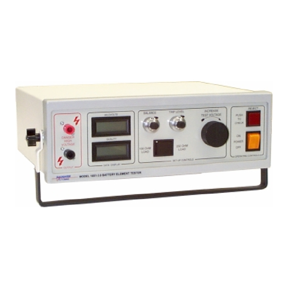
Introduction This description applies to the Model 1652 Surge Type Testers designed to test the dielectric strength of separators in storage battery cells. These units will give a good resolution of defective separators without false rejects due to moisture in damp process plates. -
Page 4: Controls And Indicators
Line Cord, and the removable Fuse Drawer, which is tan. 11. Reject Indicator(s) – The Model 1652 has three (3) Reject Indicators; on the front panel, a Red illuminated button, on the rear panel, an Audible Tone and a 9- pin D-sub connector provides a Dry Contact Closure when a reject occurs. -
Page 5: Input Power Adjustment
fig. 1 Input Power Adjustment The input power setting is visible in a small window in the fuse drawer. To change the input voltage setting, proceed as outlined below. 1. Switch tester off and unplug the line cord from the utility mains and remove it from the socket-filter. -
Page 6: Theory Of Operation
Theory of Operation Pulses produced at the output terminals of the unit result from the discharge of capacitors that have been charged to a high voltage. Discharge capacitors are charged by means of a half-wave rectifier power supply operating from a high voltage transformer that is controlled on the primary side by means of the front panel voltage control. -
Page 7: Installation And Safety
Installation and Safety Caution: This unit is equipped with a three-prong grounding type line plug. It is essential that it be utilized only with a mating three-terminal receptacle, properly grounded in accordance with electrical codes. When first received, unpack the equipment carefully and inspect for any hidden damage. If damage is evident, keep the carton and file a claim with the carrier. - Page 8 Of prime consideration and importance in the layout and installation of a test station is to insure the safety both of the operator and any visitors or casual bystanders, invited or otherwise. As a general rule it is suggested that each test area be in a location with minimum distractions and not subject to extremes of temperature and moisture.
- Page 9 A final word about high voltage testers. Generally, commercial high voltage test equipment is not in itself hazardous. The hazards come about when the equipment is improperly used. These testers, when used properly and in a safe manner, can be a check on the quality and reliability of your product.
- Page 10 7. These units have dual sensitivity ranges and may be operated with the limits set to accept external loads having effective impedance in excess of 250 ohms or in excess of 100 ohms. With the 250 ohm sensitivity selected, these units are normally operated with the limit set to accept external loads having an effective resistance in excess of 260 ohms.
-
Page 11: Setup And Operation
Setup and Operation Setup adjustments should be made with no load connected to the test prods. Proceed as follows: 1. Turn the unit ON. 2. Adjust voltage to desired Peak Kilovolts reading. One (1.00) kilovolt = 1000 volts. 3. Adjust Balance to make quality meter read 000. Set the trip level to 10.0. 4. - Page 12 8. When replacing the obsolete Model A648/018 (018) tube type battery element tester with a Model 1652 solid state tester, it is usually necessary to increase the test voltage by 100 to 200 volts depending upon cell capacitance. This apparent difference in test voltage is caused by the different trigger characteristics of the thyratron tube and SCR and the solid state metering circuit.
-
Page 13: Maintenance
Maintenance Routine maintenance should include the following: 1. Function Check At least once per shift verify calibration by the methods described in the “Installation and Safety” on page 7. 2. Safety Inspection A. Daily – Check test leads for damage. Retracting probes should be inspected for contamination or burning inside barrel by bringing the tips together in the retracted position at full voltage. -
Page 14: Repairs
Repairs This equipment is rather complex. Field repairs, other than routine replacement test probe assemblies and fuses are not recommended due to the risk of high voltage shock. It is recommended that defective equipment be returned to the factory for repair where complete calibration and repair services are offered at our Ardmore, Oklahoma facility. - Page 15 1 YEAR LIMITED WARRANTY POLICY All products are covered by our standard limited warranty: Your new instrument is warranted to be free from defects in workmanship and material for a period of (1) year from date of shipment and we will repair or replace any such product we find to be so defective upon its prepaid return to us.
- Page 16 This page intentionally left blank.
Need help?
Do you have a question about the 1652 and is the answer not in the manual?
Questions and answers