Table of Contents
Advertisement
Quick Links
INSTALLATION AND MAINTENANCE INSTRUCTIONS
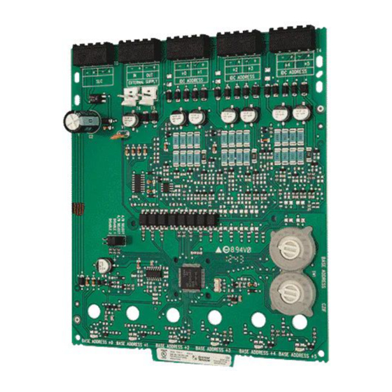
NZM-100-6 Six Zone Interface Module
SPECIFICATIONS
Normal Operating Voltage:
Stand-By Current:
Alarm Current:
Temperature Range:
Humidity:
Dimensions:
Accessories:
Wire Gauge:
Maximum IDC Wiring Resistance:
External Power Supply Voltage:
Ripple Voltage:
IDC (supervised and power limited)
DC Voltage:
Frequency:
Alarm Current:
Standby Current 6 circuits:
BEFORE INSTALLING
This information is included as a quick reference installation guide. Refer to
the appropriate control panel installation manual for detailed system informa-
tion. If the modules will be installed in an existing operational system, inform
the operator and local authority that the system will be temporarily out of ser-
vice. Disconnect the power to the control panel before installing the modules.
This system contains static sensitive components. Always ground yourself
with a proper wrist strap before handling any circuits so that static charges are
removed from the body. The module housing should also be grounded.
NOTICE: This manual should be left with the owner/user of this equipment.
COMPATIBLE TWO-WIRE SYSTEM SENSOR SMOKE DETECTORS FOR USE WITH NZM-100-6 WITH ZONE A IDENTIFIER
** 2100AT
* 2W-B
* 2W-TB
DH100LP
* Class B Only
** No Accessory will be supported by 2100AT
15-32 VDC
2.3 mA @ 24 V
40 mA (assumes all six LEDs solid on)
32°F to 120°F (0°C to 49°C)
10 to 93% Non-condensing
6.8˝H x 5.8˝W x 1.25˝D
CH-6 Chassis; BB-25 Cabinet; ;
BB-XP Cabinet; CAB-4 Series Cabinets; CAB-3 Series Cabinets
12-18 AWG
25 Ohms
Regulated 24 VDC
0.1 volts RMS maximum
18-28 volts power limited
DC
90mA per circuit
42mA Maximum @18 VDC
56mA Maximum @24 VDC
66mA Maximum @28 VDC
DET.
DETECTOR
MODEL
COMP. ID
MANUFACTURER
1151
A
SYSTEM SENSOR
1451
A
SYSTEM SENSOR
1451DH
A
SYSTEM SENSOR
2151
A
SYSTEM SENSOR
2451
A
SYSTEM SENSOR
2451TH
A
SYSTEM SENSOR
5451
A
SYSTEM SENSOR
1100
A
SYSTEM SENSOR
1400
A
SYSTEM SENSOR
A
SYSTEM SENSOR
2100B
A
SYSTEM SENSOR
2100D
A
SYSTEM SENSOR
2100S
A
SYSTEM SENSOR
2100TB
A
SYSTEM SENSOR
2100TD
A
SYSTEM SENSOR
2100TS
A
SYSTEM SENSOR
2300B
A
SYSTEM SENSOR
2300TB
A
SYSTEM SENSOR
2400
A
SYSTEM SENSOR
2400TH
A
SYSTEM SENSOR
A
SYSTEM SENSOR
A
SYSTEM SENSOR
A
SYSTEM SENSOR
GENERAL DESCRIPTION
The NZM-100-6 Six Zone Interface Module is intended for use in an intelli-
gent alarm system. Each module provides an interface between the intelligent
alarm system and a conventional alarm system loop. A common SLC input is
used for all modules, and the initiating device loops share a common super-
visory supply and ground. Otherwise, each monitor operates independently
from the others. Each module has its own unique address.
A pair of rotary code switches is used to set the address of the first module
from 01 to 154. The remaining modules are automatically assigned to the next
five higher addresses. Provisions are included for disabling a maximum of two
BASE MODEL
B110LP,B401
B401, B401B
DH400
B110LP, B401
DH400, B401B,B401
B401, B401B
B401
N/A
N/A
N/A
N/A
N/A
N/A
N/A
N/A
N/A
N/A
N/A
N/A
N/A
N/A
N/A
N/A
1
12 Clintonville Road
Northford, CT 06472-1653
Phone: 203.484.7161
MAX DET.
20
20
20
20
20
20
20
20
20
20
20
20
20
20
20
20
20
20
20
20
20
20
20
I56-2990-004
7/1/2022
Advertisement
Table of Contents

Related Manuals for Honeywell Notifier NZM-100-6


Summary of Contents for Honeywell Notifier NZM-100-6
- Page 1 INSTALLATION AND MAINTENANCE INSTRUCTIONS 12 Clintonville Road NZM-100-6 Six Zone Interface Module Northford, CT 06472-1653 Phone: 203.484.7161 SPECIFICATIONS Normal Operating Voltage: 15-32 VDC Stand-By Current: 2.3 mA @ 24 V Alarm Current: 40 mA (assumes all six LEDs solid on) Temperature Range: 32°F to 120°F (0°C to 49°C) Humidity:...
- Page 2 Cabinets unused modules to release the addresses to be used elsewhere. Each mod- ule also has panel controlled bicolor LED indicators. The panel can cause the A BB-25, CAB-3, or CAB-4 Series cabinet will house the CH-6 chassis with up LEDs to blink, latch on, or latch off.
- Page 3 FIGURE 7. Step 2: Carefully swing the upper edge of the board back towards the back of the chassis until it touches the two standoffs. Step 3: Align two 4-40 screws with the two standoffs and tighten. Step 4: Address and wire the modules according to the instructions in this manual.
- Page 4 FIGURE 8. INTERFACE TWO-WIRE CONVENTIONAL DETECTORS – CLASS B CONNECT MODULES TO BASE ADDRESS LISTED COMPATIBLE FIRE•LITE CONTROL 6 7 8 9 6 7 8 9 PANELS ONLY 3.9K EOL RESISTOR (INCLUDED) – – CLASS B IDC (TYPICAL) TO PANEL CONTROLLED (–) RESETTABLE POWER SUPPLY POWER-LIMITED...
- Page 5 FIGURE 10. EXAMPLE OF MULTIPLE BOARDS SHARING SAME EXTERNAL SUPPLY Refer to figures 8 and 9 for typical wiring. Make certain lip on long power supply jumper engages retaining tab on T5 or T6 as shown in View A-A. PCB 1 PCB 2 —...
- Page 6 – Connect the equipment into an outlet on a circuit different from that to which the receiver is connected. – Consult the dealer or an experienced radio/TV technician for help. NOTIFIER® is a registered trademark of Honeywell International, Inc. I56-2990-004...
Need help?
Do you have a question about the Notifier NZM-100-6 and is the answer not in the manual?
Questions and answers