
Subscribe to Our Youtube Channel
Related Manuals for RKI Instruments 65-2670-CL2-04


Summary of Contents for RKI Instruments 65-2670-CL2-04
- Page 1 65-2670XL-XX-07 M2A-XL Transmitter Operator’s Manual Part Number: 71-0617 Revision: P1 Released: 11/14/22 RKI Instruments, Inc. www.rkiinstruments.com...
- Page 2 WARNING Read and understand this instruction manual before operating instrument. Improper use of the gas monitor could result in bodily harm or death. Periodic calibration and maintenance of the gas monitor is essential for proper operation and correct readings. Please calibrate and maintain this instrument regularly! Frequency of calibration depends upon the type of use you have and the sensor types.
- Page 3 Product Warranty RKI Instruments, Inc. warrants gas alarm equipment sold by us to be free from defects in materials, workmanship, and performance for a period of one year from date of shipment from RKI Instruments, Inc. Any parts found defective within that period will be repaired or replaced, at our option, free of charge.
-
Page 4: Table Of Contents
Table of Contents Chapter 1: Introduction ..........6 Overview . - Page 5 Chapter 7: Maintenance ..........38 Overview.
-
Page 6: Chapter 1: Introduction
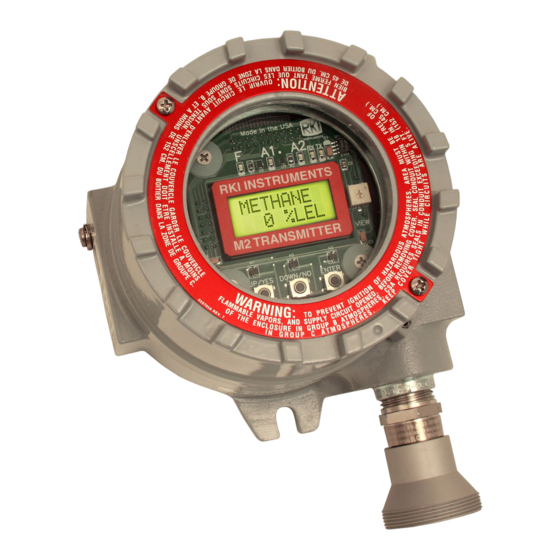
Chapter 1: Introduction Overview This chapter briefly describes the 65-2670XL-XX-07 M2A-XL Transmitter. This chapter also describes the 65-2670XL-XX-07 M2A-XL Transmitter Operator’s Manual (this document). Table 1 at the end of this chapter lists the specifications for the M2A-XL. About the M2A-XL Transmitter The M2A-XL transmitter is a fixed mount, continuous-monitoring detector head. -
Page 7: Specifications
Specifications Table 1 lists specifications for the M2A-XL. Table 1: M2A-XL Specifications • Ammonia (NH ): 0 - 75.0 ppm, 0.1 ppm increments • Ammonia (NH ): 0 - 100 ppm, 1 ppm increments • Ammonia (NH ): 0 - 200 ppm, 1 ppm increments •... - Page 8 Table 1: M2A-XL Specifications Operating -20°C to 40°C Temperature Accuracy ± 10% of reading or ± 5% of full scale (whichever is greater) These are the RKI factory settings. You can change the alarm settings in Configuration Mode. See “Viewing & Changing M2A-XL Parameters” on page 31. WARNING: When using the M2A-XL, you must follow the instructions and warnings in this manual to assure proper and safe operation of the M2A-XL and to minimize the risk of personal injury.
-
Page 9: Chapter 2: Description
Chapter 2: Description Overview This chapter describes the components of the M2A-XL transmitter. The transmitter is a 4 - 20 mA type detector head. It consists of the detector, calibration adapter/splash guard, terminal PCB, the M2A-XL junction box, and the detector junction box. The two-junction-box configuration is intended for situations where the detector needs to be installed at an inaccessible location. - Page 10 The table below outlines the M2A-XL part numbers and replacement detector part numbers for the detectors. M2A-XL Part Target Gas, Range Detector Used Number , 0 - 3 ppm 65-2670-CL2-04 65-2302-CL2 , 0 - 10 ppm 65-2670-CL210-4 65-2302-CL2-10 , 0 - 1 ppm 65-2670-CLO2-04...
- Page 11 Detector Housing Body (different for each detector type) Cap Gasket Plug-in Sensor Hydrophobic Membrane Detector Housing Cap Figure 2: Detector Component Location Detector Housing Body The detector housing body protects the electronic components within the housing. Use the mounting threads at the top of the housing to screw the detector into the 3/4 NPT hub on the bottom of the detector junction box.
-
Page 12: Internal Description
M2A-XL include the terminal PCB which provides for all the wiring connections to the M2A-XL and the control PCB which displays the gas reading and has the control buttons. 3/4 NPT Conduit Opening, Plugged Control PCB Terminal PCB RKI INSTRUMENTS 3/4 NPT Conduit Opening for Wire Entry M2A-XL T RANSMITTER M2A-XL Junction Box... - Page 13 Two columns of plug-in style terminal strips are used to make all wiring connections to the M2A- XL. The column on the left consists of the power/signal, detector, and Modbus terminal strips. The column on the right consists of the relay terminal strips. A 20 position connector at the bottom of the terminal PCB is used to connect the terminal PCB to the control PCB with a ribbon cable.
- Page 14 PCB mounting standoffs and pushing it onto the banana jacks. The jacks retain the control PCB. Alarm 1 LED Alarm 2 LED RX LED Fail LED TX LED Magnetic Switches ENTER DOWN/NO RKI INSTRUMENTS UP/YES M2A-XL TRANSMITTER Push Button Control Switches OLED Display UP/YES DOWN/NO ENTER Figure 5: Control PCB Component Location 14 •...
- Page 15 OLED Display The OLED display is located at the top of the control PCB. It indicates the current gas reading and displays messages and parameters in the M2A-XL’s programs. Control Buttons The M2A-XL includes three push button switches that allow you to enter the M2A-XL’s operating modes, navigate through the modes, update settings, and save changes to the settings.
- Page 16 Status LEDs The M2A-XL includes five status LEDs that are located above the display (see Figure 5). • Fail LED The fail LED turns on when the M2A-XL is experiencing a fail condition. A fail condition can be caused by a detector failure or low detector signal. •...
-
Page 17: Chapter 3: Installation & Startup
Chapter 3: Installation & Startup Overview This chapter describes procedures to mount the M2A-XL Transmitter in the monitoring environment and wire it to input power and devices. Mounting the M2A-XL Transmitter 1. Select a mounting site that is representative of the monitoring environment. Consider the following when you select the mounting site. -
Page 18: Wiring The M2A-Xl Transmitter
Ø3.65 2.70 3/4 Conduit Hub 5.25 6.70 Max Rubber Spacer, Detector 1.13 Figure 7: Detector Junction Box Dimensions 3. Tubing from the calibration adapter/splash guard must be 1/8 inch I.D. x 1/4 inch O.D. Teflon. Install a small piece of 3/16 inch I.D. flexible polyurethane tubing to each end of the Teflon tubing. - Page 19 5. Gently pull until the control PCB is pulled away from the banana jacks. Take care not to pull too hard and damage the cable which connects the control and terminal PCBs. 6. Let the control PCB hang by the cable. The terminal strips are now visible on the terminal PCB.
- Page 20 3/4 NPT Conduit Opening Cable Shield Detector Term inal Strip Black Table M2A-XL J-Box Black Table Gas Type Table Detector J-Box Gas Type + W ire yellow Detector CLO2 v iolet white Calibration Adapter/Splash G uard SO 2 blue Figure 8: Wiring the Detector to the M2A-XL 14.
- Page 21 Wiring the M2A-XL to a Controller and Alarm Devices 1. Guide multi conductor shielded cable or cables or wires in conduit through the left conduit hub of the M2A-XL junction box. The number of cables or wires needed will depend on whether the M2A-XL is wired to a gas monitoring controller or just to power, whether any relays are used, and whether the Modbus output is used.
-
Page 22: Start Up
See Figure 9 below for field wiring connections to the M2A-XL. Alarm Device RKI Controller Power Terminals Fail Alarm (24 VDC) + Device 4 - 20 mA In (S) Alarm 1 (24 VDC) - Alarm Device Detector Wiring Alarm 2 Alarm Device Modbus Typical Alarm... - Page 23 “Adjusting the Fresh Air Reading.” Adjusting the Fresh Air Reading When the M2A-XL is shipped from RKI Instruments, Inc., it is factory calibrated. If a full calibration is desired at startup, see “Calibration” on page 41.
- Page 24 WARNING: The M2A-XL is not an active gas monitoring device during the fresh air adjustment procedure. The 4-20 mA output signal will “freeze” at 3.5 mA and all relays will remain in their non-alarm state while the M2A-XL is in Calibration Mode.
-
Page 25: Chapter 4: Operation
Chapter 4: Operation Overview This chapter describes the M2A-XL in normal operation. This chapter also describes the M2A- XL in alarm 1, alarm 2, and fail conditions and suggests responses to these conditions. Normal Operation Normal operation is defined as follows: •... -
Page 26: 4 - 20 Ma Signal Output Operation
4 - 20 mA Signal Output Operation The output at the S terminal of the power/signal terminal strip is a 4 - 20 mA signal that corresponds to the detection range of the M2A-XL. During normal operation, this signal tracks the gas concentration on the OLED display. -
Page 27: Alarm Indications
Alarm Indications NOTE: The M2A-XL includes alarm on and alarm off delay settings for alarm 1 and alarm 2. The alarm indications described in this section operate according to the factory set alarm settings. See Table 5 on page 31 for all the factory settings. Table 4: Visual and Audible Alarm Indications Condition Cause... - Page 28 Alarm 1 Condition Alarm 1 Condition Indications When the gas reading reaches the alarm 1 setpoint, the M2A-XL senses an alarm 1 condition. The M2A-XL alerts you to an alarm 1 condition as follows: • The A1 LED turns on. •...
- Page 29 Responding to an Alarm 2 Condition 1. Follow your established procedure for a high level toxic gas condition. 2. After the gas reading falls below the alarm 2 setpoint, press the ENTER button to reset the alarm circuit. Resetting the alarm circuit turns off the A2 light, resets the OLED display, and de-energizes the alarm 2 relay.
- Page 30 Low Power Alarm Low Power Alarm Indications The M2A-XL senses a low power condition when the DC power source is 9.5 volts or less. WARNING: While in a low power condition, the M2A-XL is not an active gas monitor. When the M2A-XL senses a low power condition, it alerts you as follows: •...
-
Page 31: Chapter 5: Configuration Mode
Chapter 5: Configuration Mode Overview This chapter describes how to view and change M2A-XL parameters using Configuration Mode. It is accessed using the program buttons. Configuration Mode includes a 5-minute time-out feature. If you do not press a control button for 5 minutes, the M2A-XL automatically returns to normal operation. - Page 32 Table 5: Configuration Parameters Parameter Description (Factory Set Value) ALARM-1 (activation) Indicates if the alarm 1 circuit is activated by gas readings (Increase) increasing (Increase) or decreasing (Decrease) to the ALARM-1 Level. ALARM-1 (relay action) If set as N. DE-EN, the alarm 1 relay is de-energized in normal (N.
- Page 33 Table 5: Configuration Parameters Parameter Description (Factory Set Value) A2 OnDy (alarm 2 on delay) The amount of time the M2A-XL delays activation of the alarm 2 (1 secs) circuit once an alarm 2 condition is initiated. It can be set in 1 second increments from 0 - 60 seconds, in 1 minute increments from 1 - 15 minutes, and in 15 minute increments from 15 - 60 minutes.
- Page 34 5. If you do not wish to save the adjustments and want to exit Configuration Mode, press and release the DOWN/NO button. The DO OVER? YES/NO message will display. Press and release the DOWN/NO button. The ABORT? YES/NO message will display. Press the UP/ YES button to return to normal operation.
-
Page 35: Chapter 6: Gas Type Mode
Chapter 6: Gas Type Mode Overview This chapter describes how to use Gas Type Mode to select the M2A-XL’s gas type. The gas type determines the target gas and detection range. CAUTION: The target gas is factory set and does not normally need to be changed. Gas Type Mode includes a 5-minute time-out feature. - Page 36 Table 6: Gas Types Gas Type Detection Range Choices 0 - 75.0 ppm 0 - 6.00 ppm ASH3 0 - 1.50 ppm 0 - 50.0 ppm CLO2 0 - 1.00 ppm CLO2 0 - 3.00 ppm 0 - 500 ppm 0 - 200 ppm 0 - 15.0 ppm CLO2...
- Page 37 8. To save the configuration settings, press and release the UP/YES button.The display will indicate Config Saved and the M2A-XL will begin its warm-up sequence. To discard the settings and review them again, press the DOWN/NO button. The display will ask DO OVER? YES/NO. Press the UP/YES button and the display will indicate Re- do Config, then display the target gas and the detection range for a few seconds before returning to Configuration Mode.
-
Page 38: Chapter 7: Maintenance
Chapter 7: Maintenance Overview This chapter describes procedures for performing preventive maintenance, troubleshooting, calibrating the M2A-XL, and replacing field replaceable parts. Preventive Maintenance This section describes a recommended preventive maintenance schedule to ensure the optimum performance of the M2A-XL. It includes daily and quarterly procedures. Daily Verify a display reading of 0 ppm. - Page 39 Table 7: Troubleshooting the Detector Condition Symptom(s) Probable Causes Recommended Action • The M2A-XL is 1. Verify that the M2A-XL wiring is Frequent or The M2A-XL alerts experiencing false properly shielded. See “Wiring Suspect you to frequent or readings due to RFI the M2A-XL Transmitter”...
-
Page 40: Calibration Frequency
Although there is no particular calibration frequency that is correct for all applications, a calibration frequency of every 3 to 6 months is adequate for most transmitter applications. Unless experience in a particular application dictates otherwise, RKI Instruments, Inc. recommends a calibration frequency of every 3 months. -
Page 41: Calibration
Cl cylinder and a 0.4 factor. • If a Cl cylinder is used for calibration, RKI Instruments, Inc. recommends using 2 ppm of and setting the ClO reading to 0.8 ppm. • If a ClO generator is being used, the generator’s flow rate should be set to 0.5 LPM. - Page 42 Calibration Gas Response Memory Feature The M2A-XL has the capability to “remember” the detector’s response to the calibration gas after the gas is removed from the detector during the fresh air and span adjustment procedure. This feature enables one person to perform a calibration if the detector is mounted remotely from the M2A-XL.
- Page 43 Adjusting the Fresh Air Reading CAUTION: For all gases except ClO , confirm that the detector has been running for 15 minutes before performing a calibration. For ClO , confirm that the detector has been running for 2-3 hours before performing a calibration.
- Page 44 Adjusting the Span Setting 1. If you want to continue with adjusting the span setting, press and release the UP/YES button. APPLY will alternate with SPAN Gas on the top display line and the current gas reading will be on the bottom display line. If you want to skip adjusting the span reading, press and release the DOWN/NO button.
-
Page 45: Replacing Components Of The Detector
9. The display will now alternate between the normal operation screen and the message REMOVE CAL GAS for 1 minute. If the calibration gas has not been removed from the detector, remove it now to avoid unwanted alarms. During this 1 minute period, the signal output will remain fixed at 3.5 mA and the relays will remain in their non-alarm state to avoid unwanted alarms while the calibration gas clears from the detector. - Page 46 WARNING: The sensor will not operate properly if the wire jumper is not removed. Remove jumper Figure 10: Plug-In Sensor Jumper Removal 6. Install the rubber boot and charcoal filter onto the new sensor’s face. 7. Carefully plug the replacement sensor into the four-socket pattern that is located in the detector housing.
- Page 47 Replacing the Detector NOTE: In most cases, it is only necessary to replace the plug-in sensor. 1. Turn off or unplug power to the M2A-XL. 2. Remove the detector junction box cover. 3. Disconnect the detector leads from the terminal block in the detector junction box. Note the position of the color-coded leads as you remove them.
-
Page 48: Chapter 8: Rs-485 Modbus Output
Chapter 8: RS-485 Modbus Output Overview This chapter describes the M2A-XL’s RS-485 Modbus output and how to configure the M2A-XL to make use of it. It also discusses how to wire the M2A-XL into a Modbus system. The M2A-XL provides an RS-485 serial communications interface. It is a Modbus Slave Device, supporting 2-wire RS-485 Modbus RTU serial communications. - Page 49 Ground Jumper The M2A-XL includes a 2-pin ground header (see Figure 4 on page 13) that is used when the M2A-XL is used in a Modbus system. Every M2A-XL is supplied with a ground jumper (a jumper block) installed onto this header. If the M2A-XL isn’t wired into a Modbus system or if it is wired into one as shown in Figure 12, the ground jumper should be installed.
- Page 50 Alternate Modbus Wiring For Existing Installations Although the wiring shown in Figure 11 is recommended, it is possible to wire the M2A-XL into a Modbus system with only 4 wires in situations where a pre-existing system is being replaced and wiring is already in place. This should only be done if wiring for a system that is being replaced is already installed and it is not practical to run another wire.
- Page 51 Termination Jumper The M2A-XL includes a 2-pin termination header (see Figure 4 on page 13) that is used when the M2A-XL is used in a Modbus system. Every M2A-XL is supplied with a termination jumper (a jumper block) installed onto this header. If the M2A-XL is not used in a Modbus system, this jumper has no function.
-
Page 52: Using The M2A-Xl In A 4-Wire Modbus System
Using the M2A-XL in a 4-wire Modbus System Although the M2A-XL is a 2-wire Modbus RTU device, it can be used with a 4-wire Modbus controller if the system wiring is modified as follows: • Connect the controller’s TxD0 and RxD0 wires together and use this connection as the 2- wire Modbus D0 signal. - Page 53 Table 9: Configuration Parameters Modbus Mode Available Settings & Description Parameter Enabled/Disabled Can be set to ENABLED or DISABLED (factory setting). Enables or disables the Modbus output. Slave ID The Slave ID can be set to values from 1 (factory setting) to 247. The M2A-XL will only receive messages from the Master which are addressed to this Slave ID (except for broadcast messages which are received by all slaves).
-
Page 54: Supported Modbus Functions
Supported Modbus Functions The M2A-XL supports Function Code 03: Read Holding Registers and Function Code 16: Write Registers. Function Code 03: Read Holding Registers There are a total of 40 registers available to be read via this Function Code. Registers 1 - 2 The format (bit &... - Page 55 Table 11: Register 2, Operating State, Alarms & Relays Bit & Field Assignments (Continued) Bit(s) Value [10] Configuration Change 0=Not Changed 1=Changed Calibration Activity Flag 0=No Calibration Activity 1=Calibration Activity Has Occurred Fail Status 0 = Fail Not Asserted 1 = Fail Asserted [7:6] Alarm 2 Status 0 = No Alarm...
- Page 56 Registers 4 - 11 The 16 bytes in these registers contain the same ASCII text information that is displayed on the M2A-XL’s OLED display (not NULL Terminated). Register 12 Register 12 is the range (full scale readout). Register 13 Register 13 is the alarm 1 set point. The decimal point location is the same as specified in Register 1.
- Page 57 Register 29 Register 29 is the alarm 2 normal relay state. 0=Normally De-Energized 1=Normally Energized Register 30 Register 30 is the alarm 2 relay reset. 0=Latching 1=Self-Resetting Register 31 Register 31 is the alarm 2 ON delay. Integer values are in seconds. Register 32 Register 32 is the alarm 2 OFF delay.
- Page 58 Calibration Outcome Codes: 1=Sensor Missing 2=Sensor Too Weak 3=Signal Too Strong 4=Not Enough Span 5=Negative Reading 6=Span Gas Value Is Not OK 7=Calculated Zero Is Too Low 8=Calculated Zero Is Too High 9=Zero Failure 10=Span Failure 11=Calibration Is Overscale 12=LEL Sensor Offset Is Too High 13=LEL Null Operation Failed 14=Operation Not Performed Register 39...
-
Page 59: Chapter 9: Parts List
Chapter 9: Parts List Table 13 lists replacement parts and accessories for the M2A-XL Transmitter. Table 13: Parts List Part Number Description 06-1248RK Calibration kit sample tubing (3/16 in. x 5/16 in.; specify length when ordering) 07-0039RK Detector housing cap gasket 18-0400RK-01 Detector junction box, with spacers 18-0440-01-01... - Page 60 Table 13: Parts List Part Number Description 65-2302-NH3-5 CT-7 Series detector, 0 - 500 ppm ammonia (includes sensor) 65-2302-SO2-10 Replacement detector assembly, SO , 0 - 10 ppm range (includes plug-in sensor) 71-0518 65-2670XL-XX-07 M2A-XL Transmitter Operator’s Manual (this document) 81-0076RK-01 Zero air calibration cylinder, 34 liter steel 81-0076RK-03...
-
Page 61: Appendix A: Control Button Quick Reference Guide
Appendix A: Control Button Quick Reference Guide The M2A-XL’s control buttons allow access to operational modes, resetting of alarms, and display of the Information Screen. Table 14 shows which button combinations perform these functions and which parameters are available for adjustment while in the operational modes. While in these modes, display prompts showing a “?”... -
Page 62: Appendix B: Plc And Dcs Device Wiring
Appendix B: PLC and DCS Device Wiring The M2A-XL can be wired to a PLC or DCS device if desired. 1. Guide multi conductor shielded cable or cables or wires in conduit through the top conduit hub of the junction box. The number of cables or wires needed will depend on whether any relays are used and whether the Modbus output is used. - Page 63 • If the M2A-XL will be wired into a Modbus network, see “Chapter 8: RS-485 Modbus Output” on page 48. See Figure 15 below for field wiring connections to the M2A-XL. 24 VDC Power Supply 24 VDC + Alarm Device Power 24 VDC - Fail Alarm...
-
Page 64: Appendix C: Function Code 16 Registers
Appendix C: Function Code 16 Registers The M2A-XL supports Function Code 16 that allows writing to the M2A-XL. There are 21 registers in this Function Code. Register 1 Register 1 is the alarm 1 set point. Value must be an integer. Any decimals are omitted. Register 2 Register 2 is the alarm 1 trigger. - Page 65 Register 9 Register 9 is the alarm 2 relay state. 0=Normally De-Energized 1=Normally Energized Register 10 Register 10 is the alarm 2 relay reset. 0=Latching 1=Self-Resetting Register 11 Register 11 is the alarm 2 ON delay. Integer value is in seconds. Register 12 Register 12 is the alarm 2 OFF delay.
- Page 66 Register 19 Register 19 is for clearing change flags. When parameters are changed at the M2A-XL, a flag is raised at the controller. This register can be used to clear those flags. Table 16: Register 19, Clear Change Flags Bit(s) Value &...
- Page 67 65-2670XL-XX-07 M2A-XL Transmitter Appendix C: Function Code 16 Registers • 67...
Need help?
Do you have a question about the 65-2670-CL2-04 and is the answer not in the manual?
Questions and answers