Advertisement
INTRODUCTION
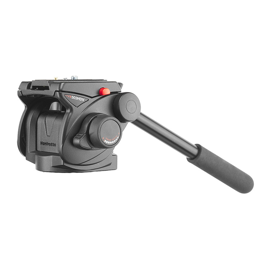
Designed for digital ENG and DVD camcorders. Also ideal for use with sport optics and telescopes. Maximum load capacity: 8kg (17.6lbs).
KEY FEATURES
- Quick release sliding plate for positioning and balancing the camcorder (with secondary safety lock)
- 1/4"W and 3/8"W camera screw and VHS pin
- 3/8" female tripod attachment
- Additional PAN and TILT drag control
- Pan bar can be fitted for left- or right-handed use
- Spirit level (with backlight) for accurate levelling
- Counterbalance system for loads up to 3.9kg/8.6lbs
SET UP


Remove the battery protection (fig. 0):
- lock knob "V"
- press clips "AB" together
- push cover "AC" up and out
- remove battery protection "AZ".
The head is supplied with the telescopic pan bar "A" (fig. 1) dismantled.
It can be mounted as shown in figure 1 by screwing knob "D" to the rosette "E"
The rosette "E" has teeth to allow the pan bar to be rotated and positioned at any 10° interval while avoiding slippage or accidental loosening. The pan bar "A" is telescopic and can be extended by means of knob "R" (fig. 1).
The head has a pan bar-mount on each side so that the pan bar "A" can be fitted to the left or right side of the head, or so that two pan bars (a spare pan bar can be purchased as an optional extra) can be mounted, one on either side of the head for two-handed control of heavier cameras:
- remove screw "W" (fig. 2)
- remove plastic protection cap "Z"
- fix the second rosette "F" with the two screws "J" using Key Allen "X" supplied
- mount pan bar "A"(or a second pan bar) by screwing knob "D" to the rosette "F" on the head
The additional rosette "F" can be used also as a spare part to replace rosette "E" (fig. 1) if the teeth become worn or damaged.
ASSEMBLING HEAD ON TRIPOD
Unlock knob "V".
Attach the head to the tripod - the head's 3/8" female thread "G" fits the screw on the top plate of the tripod. The top plate on Manfrotto tripods are also equipped with three set screws "H" which clamp against the base of the head to ensure a secure and rotation-free lock.
REMOVING QUICK RELEASE PLATE FROM HEAD

Extract plate "L" by releasing the locking knob "M", then sliding the plate out while at the same time pushing button "N" as shown in figure 3.
FITTING QUICK RELEASE PLATE TO CAMCORDER

To ensure compatibility with all camcorders, the head (fig. 3) is supplied with both a 1/4" camera screw "K" and a 3/8" camera screw "S" on the plate "L".
You should remove the screw not used by your camcorder (fig. 3):
- gently push out rubber cap "AF" with your finger
- remove the unneeded screw
- replace the rubber cap "AF" to prevent the screw from accidentally falling out and getting lost when the plate is not attached to the camcorder
NOTE: To keep the currently unneeded screw safe and together with the head ready for future use, there are two threaded housings where the screws can be stored (hole for 3/8" screw "AS" and hole for 1/4" screw "AK" - fig. 1).
Fix the camcorder onto plate "L" (fig. 4) by screwing camera 1/4" screw "K" or 3/8" screw "S" into the camcorder's threaded hole WITHOUT APPLYING EXCESSIVE FORCE (a coin can be used to tighten the screw without allowing too much leverage).
If the camcorder also has an unthreaded hole for an anti-rotation pin, insert pin "P" (fig. 3) in this hole before positioning and fastening the camera screw "K" or "S".
Before tightening the screw, ensure that the camcorder lens is aligned with the mark "LENS" on the underside of camera plate "L".
MOUNTING THE CAMCORDER ON THE HEAD


Slide the camera plate "L" into the top of the head as shown in figure 5 until the secondary safety lock button "N" clicks, then tighten knob "M".
During the following operation, hold the camcorder to prevent it from slipping backwards and forwards.
Finding the right balance point for your camcorder:
- Level the head on the tripod using the spirit level "C" (fig. 1). You can use either a tripod with a flat top plate or with a flat-topped levelling bowl.
- Loosen both plate lock knob "M" (fig. 1) and tilt lock knob "U" (fig. 6) and set the friction control "T" (fig. 6) to minimum, then slide the camcorder backwards and forwards until you find the balance point where the head remains level under the load of the camcorder (fig. 6 and 7)
- With the camcorder at the balance point, lock the plate "L" (fig. 7) in position by screwing the locking knob "M" (fig. 1)
COUNTERBALANCE SYSTEM

To balance the off-centre weight of your equipment (the weight is off-centre when you tilt the camcorder), the head is provided with a spring-loaded counterbalance system, which can be set to one of three positions or temporarily disabled.
The head has 3 counterbalance settings which correspond to different equipment weights:
counterbalance system disabled - index "OFF" (fig. 8)
1.3kg (2.8lbs) - index "1" on knob "Q"
2.6kg (5.7lbs) - index "2" on knob "Q"
3.9kg (8.6lbs) - index "3" on knob "Q"
(The counterbalance system is designed for standard camcorder weights, but the head will support loads up to 8 kg (16.2lbs) without counterbalance)
To use the counterbalance system, proceed as follows:
- unscrew knob "U" (fig. 1) while holding your equipment in order prevent it from tipping over
- with your free hand, rotate knob "Q" to index "1"
- tilt the camcorder downwards and gently let go:
- if the camcorder doesn't move, index "1" is the correct counterbalance setting for your camera
- if the equipment tips further, rotate the knob "Q" to index "2". Again, if the camcorder doesn't tip further but remains steady, this is the correct counterbalance setting.
- if the camcorder still tips downwards, rotate knob "Q" to index "3" - the maximum counterbalance setting.
REMOVING THE CAMCORDER FROM THE HEAD

 Whenever the camcorder needs to be removed from the head, hold the camera securely in one hand while opening locking knob "M", then slide the camcorder out of the head while pressing the secondary safety button "N" with the other hand.
USE

To use the head correctly, level the head on the tripod using the spirit level "C" (fig. 1). You can use either a tripod with a flat top plate or with a flat-topped levelling bowl.
The head will move through 360° pan and +90°/-60° vertical tilt movements.
Control movement accurately using the pan bar "A" (fig. 1)
- Pan movement (fig. 10) is locked by knob "V" and has an additional adjustable drag control: turn knob "Y" to increase or decrease the friction on the panoramic axis.
- Tilt (fig. 11) is locked by knob "U" and has an additional adjustable drag control: turn knob "T" to increase or decrease tilt friction.
Spirit level "C" (fig. 12) has a backlight that can be lit by pressing button "B":
press button "B" for 1 second to light the spirit level for 10 seconds
press button "B" for more than 1 second to light the spirit level for 60 seconds
Note: the light automatically turns itself off after 10 or 60 seconds, but you can switch it off manually by pressing the button "B" again.
The light also has an LED battery indicator: the red LED battery symbol next to button "B" will light when battery level drops. To change the battery (fig. 13):
- lock knob "V"
- press clips "AB" together
- push cover "AC" up and out
- replace the battery "AD" (CR1220-3V)
Note: locking knobs "M" (fig. 1) and "V" (fig. 10) can be repositioned for more comfortable use by undoing the screw at the edge of the knob with a 2.5mm tool (not supplied), removing the knob, rotating it by 1/6 of a turn and then replacing it and retightening the screw.

Documents / ResourcesDownload manual
Here you can download full pdf version of manual, it may contain additional safety instructions, warranty information, FCC rules, etc.
Download Manfrotto 503HDV - Professional Video Fluid Head Instructions
Advertisement


Need help?
Do you have a question about the 503HDV and is the answer not in the manual?
Questions and answers