
Related Manuals for Hafco Metalmaster BM-67HV


Summary of Contents for Hafco Metalmaster BM-67HV
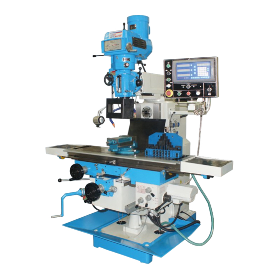
- Page 1 Page 1 Instruction Manual for BM-67HV (M621D) 02/10/2014 INSTRUCTION MANUAL BM-67HV Turret Milling Machine - Horizontal - Vertical (415V) (X) 1000mm (Y) 300mm (Z) 400mm M621D...
-
Page 2: Table Of Contents
Page 2 Instruction Manual for BM-67HV (M621D) 02/10/2014 CONTENTS 1. Safety instruction 2. Working environment and note of caution symbol 3. Usage and structure 4. Operation 5. Transmission and changing speed system 6. Main parameter 7. Bearing list 8. Adjustment 9. -
Page 3: Safety Instruction
Page 3 Instruction Manual for BM-67HV (M621D) 02/10/2014 1 Safety Instruction 1. 1 GENERAL SAFETY RULES Operator must read the instruction carefully before operating the machine, and the manager of safety department should assure the operator knows the requirements well. - Page 4 Page 4 Instruction Manual for BM-67HV (M621D) 02/10/2014 producer or qualified person can completely repair the machine. 1.1.7 Stop the machine immediately if abnormal phenomena appear, check and repair the machine by specialized persons in time. 1.1.8 Disassembly and assembly the machine with the hoisting equipment, which is of enough load capacity.
- Page 5 Page 5 Instruction Manual for BM-67HV (M621D) 02/10/2014 during operation. 1.1.18 Do not remove the guards from their working place during operation. 1.1.19 Disconnect the power supply before leaving the machine. 1.1.20 Restart the machine only after the guards and safety devices are replaced to their position and in their good function.
- Page 6 Page 6 Instruction Manual for BM-67HV (M621D) 02/10/2014 proper tool when doing this. Be sure to stop the machine when removing chips from the machine. 1.1.30 Prior to starting test operation, read this manual carefully so as to be familiar with this machine.
- Page 7 Page 7 Instruction Manual for BM-67HV (M621D) 02/10/2014 1.2.9 The operator must keep clear-minded when operating the machine and pay attention to what he is doing. It is not allowed to operate the machine when the operator is tired, after drinking or taking medicines.
-
Page 8: Working Environment And Note Of Caution Symbol
Page 8 Instruction Manual for BM-67HV (M621D) 02/10/2014 2. Working environment and note of caution symbol 2.1The milling machine is designed for operating on the site: —The height above sea level doesn’t exceed 1000m. —The ambient temperature range doesn’t exceed 5℃~40℃. - Page 9 Page 9 Instruction Manual for BM-67HV (M621D) 02/10/2014 This milling machine is designed for milling, drilling on general metal workpiece. Warning: Do not process flammable and explosive metal, e.g. pure aluminum and magnesium etc. The machine consists of body, knee, worktable, main transmission structure, feed box , ram, coolant, lubrication, electric apparatus and so on.
- Page 10 Page 10 Instruction Manual for BM-67HV (M621D) 02/10/2014...
-
Page 11: Operation
Page 11 Instruction Manual for BM-67HV (M621D) 02/10/2014 3.4 Main transmission adopts gear drive structure . 3.5 The ram consists of ram and hanging frame, the fixed base that is installed on the column, and is connected with ram through swallowtail ways, hanging frame locate the forward part of the the ram. - Page 12 Page 12 Instruction Manual for BM-67HV (M621D) 02/10/2014...
- Page 13 Page 13 Instruction Manual for BM-67HV (M621D) 02/10/2014 4.3 Three modes of the spindle sleeve feed : micro feed, power feed, manual feed 4.3.1 Microfeed First, make sure handle (6) on the left of the headstock is opposite to the position of handle (6) in Fig.
- Page 14 Page 14 Instruction Manual for BM-67HV (M621D) 02/10/2014 direction if the spindle turns clockwise . 4.3.5 No power feed when the spindle reverses. 4.4 Table feed 4.4.1 Feed box is at the bottom & at the right of the sliding saddle, and it is driven by motor.
- Page 15 Page 15 Instruction Manual for BM-67HV (M621D) 02/10/2014 power feed. 4.5 Knee Knee is in front of the column, and is connected with the column through rectangle guideways. Turn handle (1) to move knee to proper position. CAUTION: Must loosen lockhandles (21) before moving table.
- Page 16 Page 16 Instruction Manual for BM-67HV (M621D) 02/10/2014 First, loosen locknut no more than 1-2 pitches while tilting, and not too loose either. turn the worm on the right side of the headstock with spanner (S21~24), the headstock will tilt to the required position, and finally lock the locknut and start to work.
- Page 17 Page 17 Instruction Manual for BM-67HV (M621D) 02/10/2014 to horizontal spindle, so horizontal spindle can acquires 12 steps of rotation speed. 5.2 Speed change 5.2.1 Vertical spindle: First, shut off the power source before changing the speed , please adjust handle (20) on the left of the headstock to proper position according to the illustration of the scutcheon.
-
Page 18: Main Parameter
Page 18 Instruction Manual for BM-67HV (M621D) 02/10/2014 6. Main parameters Specification Parameter φ50mm (1 31/32") ( cast iron ) Max. manual drilling dia. φ12mm (15/32") (cast iron ) Max. automatic drilling dia. φ10mm ( 25/64") (steel) φ25 mm( 63/64" ) Max. -
Page 19: Bearing List
Page 19 Instruction Manual for BM-67HV (M621D) 02/10/2014 7. Bearing list of vertical and horizontal spindles (Fig. 3 ) Name Model bearing 32012/P5 bearing 7008AC/P5 bearing 16009/P6 bearing 6208-Z/P6 bearing 6305/P6 bearing 6204/P6 bearing 6304/P6 bearing 6004-Z/P6 bearing 61908-RZ/P6 bearing... - Page 20 Page 20 Instruction Manual for BM-67HV (M621D) 02/10/2014 Fig . 3...
- Page 21 Page 21 Instruction Manual for BM-67HV (M621D) 02/10/2014 Bearing list of table part (Fig. 4) Name Model Remark bearing 61901 bearing 32005 bearing 6004-2RZ bearing 6005-2RZ bearing 6004 bearing 61904-2RZ bearing 6206 bearing 7204C-Z bearing 61904-2RZ bearing 6204-Z bearing 61806-2RZ...
- Page 22 Page 22 Instruction Manual for BM-67HV (M621D) 02/10/2014 Fig . 4...
-
Page 23: Adjustment
Page 23 Instruction Manual for BM-67HV (M621D) 02/10/2014 8. Adjustment 8.1 Adjustment for longitudinal and cross guideways gibs of the table. 8.1.1 Longitudinal gib adjustment: First, loosen screw (1) on the small end of gib, then adjust screw (2 ) on the big end to proper position, tighten screw (1) properly finally.( Fig. - Page 24 Page 24 Instruction Manual for BM-67HV (M621D) 02/10/2014 Fig . 5...
- Page 25 Page 25 Instruction Manual for BM-67HV (M621D) 02/10/2014 Fig . 6...
-
Page 26: Coolant And Lubrication
Page 26 Instruction Manual for BM-67HV (M621D) 02/10/2014 9. Coolant and lubrication 9.1 The coolant pump`s flow is 25 l/minute. Coolant is sent to nozzle through coolant pipe and is forcibly sprayed to the processing workpiece by a coolant pump. - Page 27 Page 27 Instruction Manual for BM-67HV (M621D) 02/10/2014 Extinguishing Media:No. Handling and Disposal Spill Release Procedures: if a little, absorbed with sawdust, or shovel up; If a great lot, prevent spills from entering sewers, drains, soils,and reclaim spill with an approved recycling facility.
- Page 28 Page 28 Instruction Manual for BM-67HV (M621D) 02/10/2014 Fig . 7...
- Page 29 Page 29 Instruction Manual for BM-67HV (M621D) 02/10/2014 guideways, knee- column guideways and so on, should be lubricated with N46 lubricative oil at least four times every shift. 9.2.4 Bearing cover of mill holder of hanging frame adopts oil-gun injection lubrication.
-
Page 30: Transport Installation And Trial Run
Page 30 Instruction Manual for BM-67HV (M621D) 02/10/2014 Reactivity Data Stability Indicator: YES Stability Condition to avoid: Extreme heat . Materials To avoid: Strong oxidizers ,combustible material. Hazardous Polymerization Indicator: NO Handling and Di sposal Spill Release Procedures: first,cut off fire source, if a little, deal with sawdust, or shovel up;... - Page 31 Page 31 Instruction Manual for BM-67HV (M621D) 02/10/2014 Fig.8 Caution: 1. The steel-wire rope should not touch machine surface, each hand lever, handle and handwheel. Do put wood block or soft cloth on the interface between the steel-wire rope and the machine edge to avoid...
- Page 32 Page 32 Instruction Manual for BM-67HV (M621D) 02/10/2014 damaging the paint. 2. Before conveying the machine with the crane, move worktable to the front end of the knee, and keep the table`s two ends that locate on the knee have the same length, tighten the longitudinal & cross lockhandles at the same time .
- Page 33 Page 33 Instruction Manual for BM-67HV (M621D) 02/10/2014 Fig . 9...
-
Page 34: Maintenance
Page 34 Instruction Manual for BM-67HV (M621D) 02/10/2014 10.4.5 Please check whether the main motor turns right before starting the spindle and whether the feed motor phase sequence is consistent with the main motor. 10.4.6 Trial run: First, press the button to check whether each travel limit position is right and reliable,then start to idle at the lowest speed for more than 30 minutes. -
Page 35: Electrical System
Page 35 Instruction Manual for BM-67HV (M621D) 02/10/2014 clearance. 12.2 When table& knee rises and falls unstably with strange sound , check whether gibs are loose and whether the lubrication effect of the ways surface is good, adjust gib or add oil if needed. - Page 36 Page 36 Instruction Manual for BM-67HV (M621D) 02/10/2014 P o we r Fig.11 (operation panel) : horizontal spindle;...
- Page 37 Page 37 Instruction Manual for BM-67HV (M621D) 02/10/2014 : vertical spindle; : CW rotary vertical spindle; : CCW rotary vertical spindle; : milling ; : switch off. : tapping; : switch on ; : table longitudinal feed ; table up;...
- Page 38 Page 38 Instruction Manual for BM-67HV (M621D) 02/10/2014 :Emergency button; : point moving push button, it can change speed smoothly. longitudinal feed feed cross feed : counterclockwise rotation. clockwise rotation. 13.2 Electrical protection modes of the machine: Short - circuit protection, Over current protection, E-stop, O-voltage protection and power-off while door opened protection.Close spindle guard first before switching on power...
- Page 39 Page 39 Instruction Manual for BM-67HV (M621D) 02/10/2014 CCW push button (4) 、 spindle Stop push button (3) 、 conversion of horizontal horizontal spindle CW or CCW switch spindle and vertical spindle switch (1) (10) , longitudinal table feed push button (6), longitudinal table feed stop push...
- Page 40 Page 40 Instruction Manual for BM-67HV (M621D) 02/10/2014 (Fig.2 & Fig.11) WARNING : Make sure that the crank handle (1) disengages when the table automatically moves upwards or downwards . The table cannot move automatically while the locking lever (21) is locked. (Fig. 2) Table vertical movement direction (up and down)...
- Page 41 Page 41 Instruction Manual for BM-67HV (M621D) 02/10/2014...
- Page 42 Page 42 Instruction Manual for BM-67HV (M621D) 02/10/2014...
- Page 43 Page 43 Instruction Manual for BM-67HV (M621D) 02/10/2014...
- Page 44 Page 44 Instruction Manual for BM-67HV (M621D) 02/10/2014 Certif- Name Legend Specification Manufacturer icate Three-phase Lianyungang Y100L-4 3PH 380V asynchronous 50Hz 2.2kW V1 motor factory motor Three-phase Lianyungang Y100L-4 3PH 380V asynchronous 50Hz 2.2kW B3 motor factory motor Three-phase Nantong Weifen...
- Page 45 Page 45 Instruction Manual for BM-67HV (M621D) 02/10/2014 Certi- Name Legend Specification Manufacturer ficate E-stop Shanghai Tianyi LA42J-01/R button electronic co.,ltd. Push Shanghai Tianyi LA42P-01/B "S" button electronic co.,ltd. SB10 Push Shanghai Tianyi LA42P-11/W "S" button electronic co.,ltd. Push SB4、SB5 Shanghai Tianyi LA42P-11/W "S"...
-
Page 46: Accuracy List
Page 46 Instruction Manual for BM-67HV (M621D) 02/10/2014 14. Accuracy list Measure Test illustration Allowance(mm) value A: cross 0.04/1000 adjustable flatness of the machine B:longitudinal 0.04/1000 flatness of table 0.04/200 End spindle face 0.02 run out of spindle bore(Ver. /Hor.) - Page 47 Page 47 Instruction Manual for BM-67HV (M621D) 02/10/2014 15. Packing list Name Model Machine φ 16 Drilling chuck Spindle arbor Wedge shifter R8/MT3 Reduction sleeve each 1 R8/MT2 S8-10 Wrench each 1 S16-18 S21-24 Inner hexagonal spanner 5, 6 ,8 , 10...
- Page 48 Page 48 Instruction Manual for BM-67HV (M621D) 02/10/2014...
- Page 49 Page 49 Instruction Manual for BM-67HV (M621D) 02/10/2014...
- Page 50 Page 50 Instruction Manual for BM-67HV (M621D) 02/10/2014...
- Page 51 Page 51 Instruction Manual for BM-67HV (M621D) 02/10/2014 01 Column & base parts Name of item 01001 Bolt 01002 Rear cover 01003 Belt 01004 M12×65 Hexagon socket head cap screw 01005 12 Spring washer 01006 12 Plain washer 01007 Belt wheel 01008 M8×16 Set screw...
- Page 52 Page 52 Instruction Manual for BM-67HV (M621D) 02/10/2014 01 Column & base parts Name of item 01030 Indicator drop 01031 Indicator drop 01032 Taper bolt 01033 Oil gage 01034 M20×65 Hexagon socket head cap screw 01035 20 Spring washer 01036...
- Page 53 Page 53 Instruction Manual for BM-67HV (M621D) 02/10/2014 01 Column & base parts Name of item 01059 Bush 01060 46.2×3.55 Sealing ring 01061 Blanking cover 01062 Belt pulley 01063 M8×25 Hexagon socket head cap screw 01064 End cover 01065 50×90×23 Bearing...
- Page 54 Page 54 Instruction Manual for BM-67HV (M621D) 02/10/2014 01 Column & base parts Name of item 01088 Shaft 01089 Shaft 01090 Rockerarm 01091 Rockerarm 01092 12 Retaining ring 01093 4×30 Taper bolt 01094 Shifting fork 01095 Gear 01096 Gear 01097...
- Page 55 Page 55 Instruction Manual for BM-67HV (M621D) 02/10/2014 02 Knee part...
- Page 56 Page 56 Instruction Manual for BM-67HV (M621D) 02/10/2014...
- Page 57 Page 57 Instruction Manual for BM-67HV (M621D) 02/10/2014...
- Page 58 Page 58 Instruction Manual for BM-67HV (M621D) 02/10/2014...
- Page 59 Page 59 Instruction Manual for BM-67HV (M621D) 02/10/2014...
- Page 60 Page 60 Instruction Manual for BM-67HV (M621D) 02/10/2014...
- Page 61 Page 61 Instruction Manual for BM-67HV (M621D) 02/10/2014...
- Page 62 Page 62 Instruction Manual for BM-67HV (M621D) 02/10/2014...
- Page 63 Page 63 Instruction Manual for BM-67HV (M621D) 02/10/2014...
- Page 64 Page 64 Instruction Manual for BM-67HV (M621D) 02/10/2014 02 Knee Part Name of item 02001 A-M8×25 Ball knob 02002 Handle bush 02003 Handle lever 02004 M6×20 Setscrew with slotted flat end 02005 1×10×30 Pressure spring 02006 Scutcheon 02007 Shaft 02008 M8×8 Hex.
- Page 65 Page 65 Instruction Manual for BM-67HV (M621D) 02/10/2014 02 Knee Part Name of item 02030 Saddle 02031 Oil cup 02032 Pressure plate 02033 M12×65 Hexagon head bolt 02034 Washer 02035 M5×12 Cross recessed pan head screw 02036 Wiper 02037 Wiper...
- Page 66 Page 66 Instruction Manual for BM-67HV (M621D) 02/10/2014 02 Knee Part Name of item 02059 M6×16 cross recessed countersunk flat head screw 02060 8×20 Flat key 02061 Elevating screw 02062 02063 Stanchion 1.6×10 Cotter pin 02064 02065 Wrist 02066 Collar...
- Page 67 Page 67 Instruction Manual for BM-67HV (M621D) 02/10/2014 02 Knee Part Name of item 02088 Knurled screw 02089 Indexing ring 02090 Clutch 02091 1×22×30 Pressure spring 02092 Collar Handwheel 02093 02094 Washer 02095 Elastic washer 02096 M6×20 Hex. socket head bolt...
- Page 68 Page 68 Instruction Manual for BM-67HV (M621D) 02/10/2014 02 Knee Part Name of item 02117 0.8×5×16 Pressure spring 02118 Clutch 02119 20 Circlip 02120 37 Circlip 02121 Clutch 02122 Hand lever 02123 Bushing 02124 Handlebar 02125 M8×85 Hex. socket head bolt...
- Page 69 Page 69 Instruction Manual for BM-67HV (M621D) 02/10/2014...
- Page 70 Page 70 Instruction Manual for BM-67HV (M621D) 02/10/2014...
- Page 71 Page 71 Instruction Manual for BM-67HV (M621D) 02/10/2014...
- Page 72 Page 72 Instruction Manual for BM-67HV (M621D) 02/10/2014 03 Table part Name of item 03001 M6×20 Hexagon socket head cap screw 03002 6 Spring washer 03003 Spacer 03004 Handwheel 03005 1×22×30 Pressure spring 03006 Collar 03007 Dial scale 03008 Knurled screw...
- Page 73 Page 73 Instruction Manual for BM-67HV (M621D) 02/10/2014 03 Table part Name of item 03030 A6×35 Screw taper pin 03031 Shifting fork 03032 M8×12 Setscrew with hex. socket flat end 03033 Shifting block 03034 Shifting pin 03035 2×12 Cotter pin...
- Page 74 Page 74 Instruction Manual for BM-67HV (M621D) 02/10/2014 03 Table part Name of item 03059 Adjusting screw 03060 Gear cover 03061 A8×25 Screw taper pin 03062 A8×40 Screw taper pin 03063 M5×12 Cross recessed head screw 03064 Wiper 03065 Bolt...
- Page 75 Page 75 Instruction Manual for BM-67HV (M621D) 02/10/2014 03 Table part Name of item 03088 A10×26 Taper bolt 03089 20 Retaining ring 03090 Gear 03091 20×37×9 Bearing 03092 Spacer 03093 6×16 Flat key 03094 Gear 03095 35 Retaining ring 03096...
- Page 76 Page 76 Instruction Manual for BM-67HV (M621D) 02/10/2014...
- Page 77 Page 77 Instruction Manual for BM-67HV (M621D) 02/10/2014...
- Page 78 Page 78 Instruction Manual for BM-67HV (M621D) 02/10/2014...
- Page 79 Page 79 Instruction Manual for BM-67HV (M621D) 02/10/2014 04 Feeding box part Name 04001 Feeding box 04002 Oil plug 04003 A10(M16×1.5) Oil scale 04004 Cover board 04005 Spacer 04006 M6×12 Hex. socket head bolt 04007 8 Spring washer 04008 M8×25 Bolt...
- Page 80 Page 80 Instruction Manual for BM-67HV (M621D) 02/10/2014 04 Feeding box part Name Φ20×Φ16.2×1.5 Copper backing 04030 04031 M16×1.5 Oil plug 04032 Spacer 04033 Cover board 04034 Block 04035 M6×22 Hex. socket head bolt 04036 Name plate 04037 M2.5×6 Cross recessed pan head screw 04038 M6×6 Setscrew with slotted flat end...
- Page 81 Page 81 Instruction Manual for BM-67HV (M621D) 02/10/2014 04 Feeding box part Name 04059 Positioning ring 04060 6 Steel ball 04061 Spacer 04062 Worm wheel 04063 Collar 04064 Retaining ring 04065 Gear 04066 Retaining ring 04067 M6×12 Setscrew with slotted taper end Φ1×130 Iron wire...
- Page 82 Page 82 Instruction Manual for BM-67HV (M621D) 02/10/2014 04 Feeding box part Name 04088 Gear 04089 1×5×12 Pressure spring 04090 8×14 Flat key 04091 Gear 04092 Gear 04093 Gear 04094 Spline shaft 04095 Bearing cap 04096 46.2×1.8 O-Ring 04097 Gear...
- Page 83 Page 83 Instruction Manual for BM-67HV (M621D) 02/10/2014 04 Feeding box part Name 04117 Bush 04118 Shaft 04119 Shifting fork 04120 Bush 04121 Shaft 04122 Shifting fork 04123 Shaft 04124 8×25 Flat key 04125 5×16 Flat key 04126 Gear 04127...
- Page 84 Page 84 Instruction Manual for BM-67HV (M621D) 02/10/2014...
- Page 85 Page 85 Instruction Manual for BM-67HV (M621D) 02/10/2014 05 Ram part Name of item 05001 M6×10 Cross recessed pan head screw 05002 Cover board 05003 Cover board 05004 05005 05006 Adjusting screw 05007 Block 05008 Handlebar 05009 Supporting bushing 05010...
- Page 86 Page 86 Instruction Manual for BM-67HV (M621D) 02/10/2014 05 Ram part Name of item 05030 Conical bolt 05031 6 Washer 05032 6 Nut 05033 16 Washer 05034 M16 Acorn nut...
- Page 87 Page 87 Instruction Manual for BM-67HV (M621D) 02/10/2014 06 Headstock & gear-box part 075 074...
- Page 88 Page 88 Instruction Manual for BM-67HV (M621D) 02/10/2014...
- Page 89 Page 89 Instruction Manual for BM-67HV (M621D) 02/10/2014...
- Page 90 Page 90 Instruction Manual for BM-67HV (M621D) 02/10/2014...
- Page 91 Page 91 Instruction Manual for BM-67HV (M621D) 02/10/2014...
- Page 92 Page 92 Instruction Manual for BM-67HV (M621D) 02/10/2014 06 Headstock & gear-box part Name of item 06001 Headstock 06002 Block 06003 M6×16 Hex.socket head bolt 06004 Scale 06005 2×5 Rivet 06006 Clamping block 06007 Adjustable clamping lever 06008 Spring washer 8 06009 M8×20 Hex.socket head bolt...
- Page 93 Page 93 Instruction Manual for BM-67HV (M621D) 02/10/2014 06 Headstock & gear-box part Name of item 06030 Bracket 06031 3×14 Spring pin 06032 Bracket 06033 A4×18 Taper pin 06034 M6×20 Hex.socket head bolt 06035 Oil cup M6 06036 A6×45 Screw taper pin 06037 M6×35 Hex.socket head bolt...
- Page 94 Page 94 Instruction Manual for BM-67HV (M621D) 02/10/2014 06 Headstock & gear-box part Name of item 06059 Scale 06060 M6×60 Hex.socket head bolt 06061 Bevel gear 06062 Cover 06063 M6×8 Slotted pan head screw 06064 M12×30 Hex.socket head bolt 06065...
- Page 95 Page 95 Instruction Manual for BM-67HV (M621D) 02/10/2014 06 Headstock & gear-box part Name of item 06088 56×2.65 O-Ring 06089 Cover 06090 M6×6 Setscrew with slotted taper end 06091 Shaft 06092 8×20 Flat key 06093 Cover 06094 6304 Bearing 06095...
- Page 96 Page 96 Instruction Manual for BM-67HV (M621D) 02/10/2014 06 Headstock & gear-box part Name of item 06117 Spacer 06118 6204 Bearing 06119 47 Retaining ring for hole 06120 6003 Bearing 06121 45 Shaft retaining ring 06122 Gear 06123 Gear 06124 6×20 Flat key...
- Page 97 Page 97 Instruction Manual for BM-67HV (M621D) 02/10/2014 06 Headstock & gear-box part Name of item 06146 75 Retaining ring for hole 06147 Collar 06148 85×2.65 O-Ring 06149 M39×1.5 Round nut 06150 39 Check washer 06151 Spacer 06152 7008AC Bearing...
- Page 98 Page 98 Instruction Manual for BM-67HV (M621D) 02/10/2014 06 Headstock & gear-box part Name of item 06175 4×52×42 Pressure spring 06176 Spline sleeve 06177 3 Spring washer 06178 M3×10 Hex.socket head bolt 06179 06180 Clutch 06181 Gear 06182 Collar 06183...
- Page 99 Page 99 Instruction Manual for BM-67HV (M621D) 02/10/2014 06 Headstock & gear-box part Name of item 06204 8×36 Flat key 06205 Gear 06206 M5×10 Cross-recessed countersunk head screw 06207 Spacer 06208 6202 Bearing 06209 Gear 06210 Cover 06211 5×14 Flat key...
- Page 100 Page 100 Instruction Manual for BM-67HV (M621D) 02/10/2014 06 Headstock & gear-box part Name of item 06233 Shifting fork 06234 Collar 06235 Shaft 06236 Shifting fork(shifting block)...
- Page 101 Page 101 Instruction Manual for BM-67HV (M621D) 02/10/2014 09 Cooling part...
- Page 102 Page 102 Instruction Manual for BM-67HV (M621D) 02/10/2014 09 Cooling part Name of item 09001 Cover 09002 M4×10 Cross recessed pan head screw 09003 Cover 09004 Union joint Φ13×Φ10.2×1.5 Copper backing 09005 09006 M10×1 Oil plug 09007 Container 09008 Cooling pump seat...
- Page 103 Page 103 Instruction Manual for BM-67HV (M621D) 02/10/2014...
- Page 104 Page 104 Instruction Manual for BM-67HV (M621D) 02/10/2014 10 Table lubrication part Name of item 10001 M8×1 Lubrication pump 10002 M6×25 Hexagon socket head cap screw 10003 Oil pipe with protecting sheath 10004 M8×1—Φ4.2 Fuel pipe union Φ6×Φ4.1 Dual taper cutting sleeve...
- Page 105 Page 105 Instruction Manual for BM-67HV (M621D) 02/10/2014...
- Page 106 Page 106 Instruction Manual for BM-67HV (M621D) 02/10/2014 F1 Accessories part Name of item F1001 Draw bar F1002 Horizontal milling bar F1003 Distance sleeve F1004 Distance sleeve F1005 Distance sleeve F1006 Distance sleeve F1007 Axle box F1008 Supporting sleeve F1009...
Need help?
Do you have a question about the BM-67HV and is the answer not in the manual?
Questions and answers