
Related Manuals for THORLABS WFS150


Summary of Contents for THORLABS WFS150
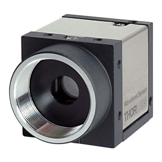
- Page 1 Operation Manual Thorlabs Instrumentation Optical Wavefront Sensor WFS150 / WFS150C 2007...
- Page 2 Version: Date: December, 2007 © <2007> ... Thorlabs GmbH © <2007> ... Thorlabs GmbH...
-
Page 3: Table Of Contents
3 WEEE ........................... 6 Waste Treatment on your own Responsibility ................................. 7 Ecological Background ................................. 7 Part II Getting Started 1 WFS150/WFS150C Quick Start-up ........................... 9 Software Installation ................................. 9 Connection to the PC ................................. 18 Start the Application ................................. 22... - Page 4 1 Zernike Fit and Zernike Modes ........................... 109 2 Microlens Data ........................... 111 3 Typical Wavelength Curves ........................... 113 4 Wavefront Sensor Drawing ........................... 115 5 WFS Reference Position ........................... 116 6 WFS Mounting Adapter ........................... 117 Index © <2007> ... Thorlabs GmbH...
-
Page 5: Foreword
Thorlabs GmbH This part of the instruction manual contains every specific information on how to handle and use the WFS150/WFS150C Wavefront Sensor. Attention This manual contains "WARNINGS" and "ATTENTION" label in this form, to indicate danger for persons or possible damage of equipment. - Page 6 General WFS150 / WFS150C Manual Part...
-
Page 7: Part I General
All modules must only be operated with duly shielded connection USB- Cables delivered by Thorlabs. Only with written consent from Thorlabs may changes to single components be carried out or components not supplied by Thorlabs be used. This precision device is only transportable if duly packed into the complete original packaging including the plastic form parts. -
Page 8: Weee
· left over parts of units disassembled by the user (PCB's, housings etc.). · If you wish to return a Thorlabs unit for waste recovery, please contact Thorlabs or your nearest dealer for further information. © <2007> ... Thorlabs GmbH... -
Page 9: Waste Treatment On Your Own Responsibility
Waste Treatment on your own Responsibility If you do not return an "end of life" unit to Thorlabs, you must hand it to a company specialized in waste recovery. Do not dispose of the unit in a litter bin or at a public waste disposal site. - Page 10 Getting Started WFS150 / WFS150C Manual Part...
-
Page 11: Part Ii Getting Started
· USB 2.0 high speed port (A USB 1.1 full speed port is not usable!) There is only one software component that must be properly installed and activated in order to allow USB control of your WFS150/WFS150C Wavefront Sensor. This software must be installed prior to make any electrical connections between the Wavefront Sensor and PC via USB interface. - Page 12 Wavefront Sensor hardware. 1. Installing the Sensor USB Drivers Don't wonder that a driver for a Thorlabs DCU USB2.0 camera is being installed. This is correct because the Wavefront Sensor uses such a camera and therefore the same drivers.
- Page 13 Click 'Next' to proceed. It is sufficient to choose 'Drivers' in order to install the required camera drivers only. A complete installation of the camera application software and its documentation is not necessary. Click 'Next' to proceed. © <2007> ... Thorlabs GmbH...
- Page 14 WFS150 / WFS150C Manual Click 'Next' to proceed or select an alternative folder where to install the driver. Let the destination folder name unchanged and click 'Next'. © <2007> ... Thorlabs GmbH...
- Page 15 Getting Started Click 'Next' and the installation process starts. The following panel will appear. Let the options enabled to generate shortcuts to the uc480Viewer software and click 'Next'. Click 'Next' to proceed. © <2007> ... Thorlabs GmbH...
- Page 16 WFS150 / WFS150C Manual The 'WhatsNew.txt' file will inform you about latest changes of the camera software, it can be disabled. Click 'Next' to proceed. If it is required to restart your computer leave option 'Yes' enabled and click 'Finish' to reboot the computer.
- Page 17 Click on 'Install Wavefront Sensor Application Software' to start the installation procedure. The following opening screen will appear: Click 'Next' to proceed. Read the License Agreement carefully. Mark 'I accept the License Agreement' and click 'Next' to proceed. © <2007> ... Thorlabs GmbH...
- Page 18 WFS150 / WFS150C Manual You will be informed about items that are going to be installed. Click 'Next' to proceed. The installation process will take a minute. If no error occurs the following message appears: © <2007> ... Thorlabs GmbH...
- Page 19 Getting Started Click 'Finish' to complete the installation process. Depending on your operating system it may be required to restart your computer. Click 'Restart' to reboot your system. © <2007> ... Thorlabs GmbH...
-
Page 20: Connection To The Pc
After connection of the instrument Microsoft Windows® will load the appropriate drivers for the Wavefront Sensor. In fact, since the Wavefront Sensor consists of a modified Thorlabs DCU camera, the driver software is basically the same for both instruments. GAttentionG Don't worry about that a 'Thorlabs DCU camera' is displayed in the device manager. - Page 21 Getting Started Mark 'Install the software automatically (Recommended)' option and click 'Next'. Please ignore this warning '…has not passed Windows Logo testing…' and click on 'Continue Anyway'. © <2007> ... Thorlabs GmbH...
- Page 22 Click on 'Finish' to finalize the first phase. The camera hardware is now booting and the 'Found New Hardware Wizard' will appear again to assign installed drivers for the Thorlabs DCU camera: Mark 'Install the software automatically (Recommended)' option and click 'Next'.
- Page 23 From the Start button select Control Panel à System à Hardware à Device Manager. The following entry under the USB Serial Bus controllers group indicates that the Wavefront Sensor device is properly installed. © <2007> ... Thorlabs GmbH...
-
Page 24: Start The Application
As long as the driver installation is not completed or failed, the instrument will be displayed as 'uc480 boot' or unknown 'USB device'. Wait a few seconds to let the driver communicate with the instrument. If you still cannot see the entry 'Thorlabs DCU camera' please check the troubleshooting chapter. - Page 25 Description WFS150 / WFS150C Manual Part...
-
Page 26: Part Iii Description
This is done by analyzing the location and intensity of spots (spotfield) formed by imaging a beam of light onto a CCD array with a microlens array as shown in the figure below. With Thorlabs' Shack-Hartmann wavefront sensor it is possible to optimize dynamically the wavefronts of laser sources, characterize the wavefront distortion caused by optical components, and provide real-time feedback for the control of adaptive optics. - Page 27 The C-Mount threading on the face of the CCD camera allows with the help of an adapter (Thorlabs SM1A9) for the convenient mounting of ND filters, to help prevent the saturation of CCD pixel, and lens tubes to reduce scattered light and to allow for the mounting of additional optical components.
- Page 28 WFS150 / WFS150C Manual Data flow chart The following chart will give an overview that shows the data flow within the Wavefront Sensor software and also point out user defined inputs and data outputs. Color code: The brightness of the camera image is controlled within a loop to ensure an optimal saturation level.
-
Page 29: Shack-Hartmann Functional Principle
Shack-Hartmann Functional Principle The WFS150 / WFS150C Wavefront Sensor consists basically of a CCD camera with a microlens array mounted in a defined distance in front of its sensor chip. Each microlens generates a spot onto the sensor whereas the spot centroid position depends on the wavefront gradient in front of the lens area. - Page 30 WFS150 / WFS150C Manual It can be easily shown that this is caused by an incoming wavefront with the same average angle a compared to the reference wavefront. When W(x,y) describes the shape of the wavefront so its partial derivation relative...
-
Page 31: Parts List - Accessories
Both models are usable within different wavelength ranges. Due to the AR coating used inside WFS150 it is best suited within this range but not outside where the AR coating may have reflective properties! See the following Technical Data for details. - Page 32 Optional C-Mount Adapter The C-Mount threading on the face of the Wavefront Sensor allows with the help of an adapter (Thorlabs SM1A9) for the convenient mounting of components utilizing SM1 thread. These are for instance Neutral density (ND) filters, to help prevent device saturation or lens tubes to reduce scattered light and to allow for the mounting of additional optical components.
-
Page 33: Technical Data
Local Radius of Curvature > 10 mm > 7,4 mm Exposure Range 77µs – 66ms Frame Rate 15 Hz max. Image Digitization 8 bit Physical Size 32 x 34 x 45,5 mm Power Supply < 1.5W, via USB © <2007> ... Thorlabs GmbH... -
Page 34: Certifications And Compliances
WFS150 / WFS150C Manual Certifications and Compliances The Thorlabs GmbH, Hans-Böckler-Strasse 6 D-85221 Dachau, declares under it's own responsibility, that the products Wavefront Sensor WFS150, WFS150C fulfill the requirements of the following standards and therefore corresponds to the regulations of the directive. - Page 35 Operating Instruction WFS150 / WFS150C Manual Part...
-
Page 36: Part Iv Operating Instruction
PC according to Getting Started Quickly. 2. You have to connect the WFS150 / WFS150C with your PC by using the USB2.0 cable delivered by Thorlabs. As soon as the LED at the back of the Wavefront Sensor lights up green the instrument is ready for operation and you can start the application program with its Graphics User Interface (GUI). - Page 37 A beam size larger than the available aperture (5,95 x 4,76 mm) of the WFS150 / WFS150C Wavefront Sensor can be adapted using beam expanders (Thorlabs BE01 - BE20 series).
- Page 38 WFS150 / WFS150C Manual Alternatively, you can check the correct beam position also using the Spotfield Panel. Enable the diagram options 'Show Image Axes' and 'Show Pupil'. Be sure you have enabled the 'Use Beam Centroid' option within the Pupil Definitions Setup panel in order to couple the displayed pupil position to the measured beam centroid position.
- Page 39 A collimation lens (e.g. bi-convex) positioned at the distance f (its focal length) from a monomode fiber end face will generate an exactly parallel beam with a plane wavefront. © <2007> ... Thorlabs GmbH...
- Page 40 WFS150 / WFS150C Manual b) A movement of the lens towards the fiber end (or even removing the lens) generates a slightly divergent beam which increases in diameter on the way to the Wavefront Sensor. Since the speed of light is the same for all rays within a beam, the wavefront at the outer area falls back behind the center rays.
-
Page 41: Coordinate Definitions
Operating Instruction 4.2.1 Coordinate Definitions The WFS150/ WFS150C Wavefront Sensors is using a orthogonal right-hand coordinate system (x,y,z) that is defined as follows: Imagine you are within the Wavefront Sensor and are looking towards the light source. Then the x-direction points towards right and the y-direction points up whereas the optical beam to be analyzed is propagating in z direction towards the entrance aperture of the Wavefront Sensor. - Page 42 WFS150 / WFS150C Manual Within the 3D wavefront graph the beam's cross section lies within the x-y-plane that is perspectively drawn at the bottom whereas the z-axis points upwards. Imagine the beam is coming from beneath, so the displayed 3D curve will represent the wavefront at the top of the beam.
-
Page 43: The Graphics User Interface (Gui)
Troubleshooting chapter. You can also operate two or more Thorlabs Wavefront Sensors at the same time on the same computer by starting the application software again. In this case, mark the desired instrument in the list and press 'Select' or just double-click the entry. - Page 44 WFS150 / WFS150C Manual The selected Wavefront Sensor starts to work and the Graphical User Interface (GUI) displays the measured data. The GUI looks like this: The Wavefront Sensor model is displayed in the title bar of the panel. The software starts displaying the actual camera image which is called the 'Spot Field'.
-
Page 45: Operating The Wavefront Sensor Software
The following list contains all menu entries and also lists the appropriate short cut keys and toolbar symbols File Measurement File Preferences Save Measurement Data (Ctrl + S) ------------------------------------- Print Window (Ctrl + P) Print Graph Only ------------------------------------- Exit Program © <2007> ... Thorlabs GmbH... - Page 46 WFS150 / WFS150C Manual Setup Wavefront Sensor ------------------------------------- Configure Lineview Configure Spotfield Configure Beamview Configure Wavefront Graph Configure Zernike Bar Graph ------------------------------------- DataSocket Measurement Start Measurement F2 Stop Measurement F3 Calibration Plane Wavefront Spherical Wavefront ------------------------------------- Save Spotfield Reference Load Spotfield Reference...
- Page 47 Wavefront Sensor File, and only the measured Wavefront data array will be stored. This option is helpful when you want to process the â measured wavefront data for yourself using programs like Microsoft Excel © <2007> ... Thorlabs GmbH...
- Page 48 WFS150 / WFS150C Manual · Save Measurement Data (Ctrl + S) Choose drive and path for storing data within and type in a name for your Wavefront Sensor data file and click 'Save'. The content and format is defined in the 'Measurement File Preferences' panel, see above.
- Page 49 Will display a dialog panel for enabling and configuring the live transfer of measurement data via DataSocket to another application. See DataSocket for live data transfer for details. 3. Measurement The following pull down menu occurs: © <2007> ... Thorlabs GmbH...
- Page 50 WFS150 / WFS150C Manual ·Measurement Start Starts continuous Wavefront Sensor measurements and displays the results on the screen. ·Measurement Stop Stops the Wavefront Sensor measurement immediately and terminates the screen updates to keep the actual displayed graphical plots and numerical values to survey and/or save these data.
-
Page 51: Lineview Panel
Operating Instruction You were directed to the Thorlabs website at www.thorlabs.com that contains information about new software releases or related products. ·View License Agreement The Thorlabs End-User License Agreement you agreed with is displayed. ·About Shows you the actual software release versions, the Instrument Name and Serial Number of the used device. - Page 52 WFS150 / WFS150C Manual This graph is useful to check the power level of the analysed beam, especially when the automatic brightness control is disabled. Improperly manual camera settings will lead to low or saturated peak intensities or saturation. Prevent both...
- Page 53 CCD array. Enter the line number into the control 'Selected Line' to see the intensity distribution of the appropriate CCD row. The line number ranges from 0 (bottom) to the number of vertical pixels - 1. The selected line is marked within Spotfield Panel. © <2007> ... Thorlabs GmbH...
-
Page 54: Spotfield Panel
WFS150 / WFS150C Manual 4.3.2.3 Spotfield Panel The Spotfield panel allows a direct view of the image taken by the CCD camera. Intensity levels are displayed as gray scale from 0 = black to 254 digits = white and saturation is indicated by red colored pixels. - Page 55 'Show Spot Shifts' displays a short gray line between the actual spot position and its corresponding reference position. 'Show Pupil' displays a circle or an ellipse (magenta) that illustrates the actual © <2007> ... Thorlabs GmbH...
-
Page 56: Beam View Panel
WFS150 / WFS150C Manual pupil size and position. Use this panel with activated option 'Show Pupil' for interactive beam alignment to the Wavefront Sensor. Only the spots detected within the pupil will contribute to the calculation of the Zernike fit. - Page 57 Double click on the graph to see the 'Beamview Configuration' panel. 'Interpolate Spot Areas' will do an interpolation between the coarse array of measured intensity points. If switched off, the real lateral resolution becomes visible. © <2007> ... Thorlabs GmbH...
-
Page 58: Wavefront Panel
WFS150 / WFS150C Manual 'Show Image Axes' displays the center axis in horizontal and vertical direction. 'Show Beam Diameter' displays a circle or an ellipse (light gray) that illustrates the actual beam diameter and position. 'Show Pupil' displays a circle or an ellipse (magenta) that illustrates the actual pupil size and position. - Page 59 Setup, only measured wavefront data within the defined pupil are displayed. This can be advantageous in case the wavefront measurement outside the pupil is affected by low light intensity which leads to a noisy behavior. © <2007> ... Thorlabs GmbH...
- Page 60 WFS150 / WFS150C Manual Wavefront Select Switch The switch below the graph determines the wavefront type that is displayed. 'Measured' shows the wavefront which is directly calculated from the measured spot deviations using a 2-dimensional integration. 'Reconstructed' will display a wavefront that is reconstructed using all or only a selected set of the determined Zernike coefficients.
- Page 61 The x-y-plane becomes rectangular and the wavefront height is only indicated by its color. The following options define the look of the 3D graph 'Gray scale' switched between a color spectrum and a graduated gray © <2007> ... Thorlabs GmbH...
- Page 62 WFS150 / WFS150C Manual color palette 'Contour' inserts contour lines into the graph indicating lines of equal wavefront height 'Hide z axis' hides the z-axis and the corresponding grid and caption '2D Projection' let the 3D graph collapse to the base x-y plane...
-
Page 63: Zernike Coefficients Panel
The Zernike coefficients can be positive or negative and indicate that the measured wavefront does contain particular Zernike modes weighted with its coefficient standing for its amplitude. Double click on the graph to see the 'Zernike Bar Graph Configuration' panel. © <2007> ... Thorlabs GmbH... - Page 64 WFS150 / WFS150C Manual By default, the graph's vertical axis is scaled automatically. In case some of the displayed Zernike coefficients are huge compared to other distortions you like to focus on it is advantageous to switch 'Autoscale' off. Also in case of fluctuating Zernike coefficients that cause a permanently changing vertical scale, it is advantageous to disable 'Autoscale' and to define a fixed range by entering Min.
-
Page 65: Wavefront Sensor Setup Panel
To open the setup panel you can use the Menu à Setup à Wavefront Sensor entry or simply click right on one of the graphs on the right hand side of the main panel. © <2007> ... Thorlabs GmbH... -
Page 66: Camera Settings Setup
WFS150 / WFS150C Manual Changing a setup control has immediate influence to the instrument operation or data display. After finalizing changes click 'OK' to save the actual settings. Also closing the panel will automatically save the settings of all setup controls. By... - Page 67 The Wavefront Sensor is 'over filled' regarding the entrance aperture but can still yield correct results. In this case special care must be taken to the pupil parameters (see Pupil Definitions Setup). The following graph illustrates the selectable image sizes. © <2007> ... Thorlabs GmbH...
- Page 68 WFS150 / WFS150C Manual Note: Changing the camera resolution will also change the number of detectable spots. In case you are working with a 'User Calibrated Reference' a new User Calibration may be required. Depending on the selected camera resolution in pixel the resolution of the Wavefront Sensor, that is the number of the calculated microlens spots is also defined thereby.
- Page 69 The 'Exposure' time can be set to values between 0,077 ms and 66.501 ms in steps of 0.055 ms. 'Master Gain' indicates the analogue amplification factor of the CCD sensor signal, it can be set to values between 1.00 and 5.00. It is © <2007> ... Thorlabs GmbH...
- Page 70 WFS150 / WFS150C Manual advantageous to do the main brightness control using the exposure time and use low Master gain amplification factors only if the exposure control adjustment works too coarse. Otherwise the image noise will be increased needlessly. It is recommended to check the actual saturation degree of the camera's AD converter by verification on the LineView panel.
-
Page 71: Pupil Definitions Setup
To open the setup panel you can use the Menu à Setup à Wavefront Sensor entry or simply click right on one of the graphs on the right hand side of the main panel. Select the tab 'Pupil Definitions'. © <2007> ... Thorlabs GmbH... - Page 72 WFS150 / WFS150C Manual It is required to define a Zernike radius because the Zernike functions fitted to the measured wavefront are normalized to a Unity Radius = 1. Calculated Zernike coefficients refer to the here defined pupil radius (see Zernike Fit Setup).
- Page 73 Note: In case the 'Measured Wavefront' is selected for display, this option influences the total measured wavefront distortions (PV, RMS). Distortions only within the defined pupil area are usually lower that the total measured distortions outside the pupil. © <2007> ... Thorlabs GmbH...
-
Page 74: Wavefront Setup
Select the tab 'Wavefront'. Wavefront Reference The Thorlabs Wavefront Sensors WFS150 / WFS150C are factory calibrated and provide an internal reference for the measured spotfield centroids. This internal reference is based on the well known and highly accurate parameters ·... - Page 75 You can select either the absolute unit microns (µm) or relate the wavefront deformations to the operating wavelength yielding the unit waves. In the latter case you are required to input the operating wavelength in nm. © <2007> ... Thorlabs GmbH...
-
Page 76: Zernike Fit Setup
WFS150 / WFS150C Manual Switch to 'waves' unit and then input the operating wavelength of your light source. The accepted wavelength range is 200 to 1100 nm and corresponds to the wavelength range of model WFS150C. Cancel Average Wavefront Tilt In practice, the direction of the input beam is not perfectly perpendicular aligned to the sensor area. - Page 77 The best wavefront reconstruction is obtained using the highest Zernike order 10 utilizing a total number of 66 Zernike modes. Auto If 'Auto' is enabled, the Zernike order is set to the highest possible value which is © <2007> ... Thorlabs GmbH...
- Page 78 WFS150 / WFS150C Manual feasible. The highest number of Zernike modes must not exceed the amount of detected spots within the pupil. Highest order in Fourier and Optometric calculations This control can be set to 2, 4 or 6 and forces the numerical calculation of the Fourier coefficients M, J0 and J45 as well as the Optometric parameters Sphere, Cylinder and Axis to consider Zernike terms up to the desired order.
-
Page 79: Miscellaneous Setup
To open the setup panel you can use the Menu à Setup à Wavefront Sensor entry or simply click right on one of the graphs on the right hand side of the main panel. Select the tab 'Miscellaneous'. © <2007> ... Thorlabs GmbH... - Page 80 WFS150 / WFS150C Manual There are ways to speed up the Wavefront Sensor software in order to achieve a maximum Sample Rate in frames per second (fps). This may be required when the Wavefront Sensor GUI Software is used as a data...
- Page 81 Especially the lenslet tilt needs to be adjusted to below 0.01 degree in order to ensure accurate measurements of higher Zernike modes. Default Settings At first program start, the following default settings become active: · Display Graphics = off · Disable Extra Data Calculation = off © <2007> ... Thorlabs GmbH...
-
Page 82: Measurement Results
WFS150 / WFS150C Manual 4.3.4 Measurement Results Numerical measurement results are displayed on the left side of the of the main panel. Be sure that there is no error occurred during capturing the camera image and its subsequent analysis. Note: If not 'No instrument errors' appears in the status window you cannot... - Page 83 Wavefront Sensor reference plane. The higher the absolute RoC value the more flat is the corresponding wavefront and the higher is the parallelism of the beam. © <2007> ... Thorlabs GmbH...
- Page 84 WFS150 / WFS150C Manual RMS Variations Since the Zernike modes are normalized to unity variance, all Zernike coefficients of a particular order can be summarized and expressed as total RMS variation of this Zernike order. The number of Zernike orders defined in Zernike Fit Setup panel will determine the number of output appropriate RMS variation results.
-
Page 85: Measurement Warnings And Errors
Check if 'Exposure Time' and 'Gain' settings within the Camera Settings Setup panel of the camera are fixed to a manual entered level. Change the manual © <2007> ... Thorlabs GmbH... -
Page 86: User Calibration
WFS150 / WFS150C Manual setting or enable automatic control of these camera parameters. When this error occurs also for the lowest 'Exposure Time' and 'Gain' setting or if 'auto' is already enabled, the light intensity of the beam to be analyzed is too high for the Wavefront Sensor. - Page 87 Start the calibration procedure using Menu à Calibration à Plane Wavefront or simply click on the appropriate symbol in the toolbar. The following panel illustrates the required calibration setup. Click 'Do Calibration' to perform the user calibration and the following message © <2007> ... Thorlabs GmbH...
- Page 88 WFS150 / WFS150C Manual verifies successful operation. You are asked to save the reference data to a file. Click 'Yes' to store this user calibration to a predefined file within your application directory to have it available in following Wavefront Sensor sessions. Otherwise, if you click 'No' the calibration remains in memory and active but is lost as soon as the program is terminated.
- Page 89 In case the distance to the point source is measured too short or too far the following error occurs. Change the setup accordingly and repeat the calibration. After successful calibration you are asked if the reference data should be saved to a file. © <2007> ... Thorlabs GmbH...
-
Page 90: Save Measurement Data
WFS150 / WFS150C Manual Click 'Yes' to store this user calibration to a predefined file within your application directory to have it available in following Wavefront Sensor sessions. Otherwise, if you click 'No' the calibration remains in memory and active but is lost as soon as the program is terminated. - Page 91 WFS150C Serial Number M00224955 Date MM-DD-YYYY 10-11-2007 Time HH:MM:SS 11:15:17 *** CAMERA *** Camera Type Thorlabs DCU224M Camera SN 4002677159 Resolution X Resolution Y Exposure Time [ms] 0.132 Master Gain 1.089 Averages Average Type Normal © <2007> ... Thorlabs GmbH...
- Page 92 WFS150 / WFS150C Manual *** BEAM *** Beam Center X [mm] -0.003 Beam Center Y [mm] 0.011 Beam Diameter X [mm] 1.670 Beam Diameter Y [mm] 1.712 *** PUPIL *** Circular Use Beam Centroid Use Beam Dia Wavefront Calc In Pupil, Pupil Diameter X [mm] 1.500...
- Page 93 -0.035, -0.083, -0.044, 0.053, 0.229, -0.300, 0.750, 0.603, 0.329, 0.132, 0.004, -0.046, -0.008, 0.091, 0.267, -0.450, 0.807, 0.711, 0.444, 0.246, 0.117, 0.064, 0.093, 0.200, 0.376, -0.600, 0.931, 0.897, 0.628, 0.431, 0.304, 0.249, 0.277, 0.382, 0.564, © <2007> ... Thorlabs GmbH...
-
Page 94: Version And Other Program Information
4.3.8 Version and other Program Information The menu entry Help à About displays application relevant data. Visit Thorlabs website www.thorlabs.com for downloading available updates. 4.3.9 Save Instrument Settings The actual settings of the Wavefront Sensor GUI including configurations of the graphical displays and the instrument setup are automatically saved when you leave the program. - Page 95 Even when the panel is closed the server will remain active and is visible within the task bar: Before using the DataSocket server for Wavefront Sensor data transfer it has to be configured. DataSocket Server Configuration The DataSocket server needs to be configured to allow Read and Write access © <2007> ... Thorlabs GmbH...
- Page 96 WFS150 / WFS150C Manual from the connected computers. In addition, the writer application (the PC driving the Wavefront Sensor) requires rights as a creator of new data items. Open the DataSocket Server Manager using Start à Program Files à National Instruments à...
-
Page 97: Configuration Panel
Click 'Disconnect' to shut down the connection to the DataSocket server. If you 'Close' the configuration panel the data connection holds up until it is disconnected or the Wavefront Sensor application is shut down. Enable basic data © <2007> ... Thorlabs GmbH... -
Page 98: Available Data Items
WFS150 / WFS150C Manual When this check box is marked the software will continuously send setup and result data of the Wavefront Sensor measurement to the DataSocket server. See Available Data Items for a description of the available data items. - Page 99 When 'Enable wavefront data' is checked on the DataSocket configuration panel the following data items from the actual Wavefront Sensor measurement are sent to the DataSocket server. Data Item Format Unit / example Wavefront_Spots_X short Wavefront_Spots_Y short Wavefront float array (unit according to Wavefront_Unit_Um_Wav © <2007> ... Thorlabs GmbH...
-
Page 100: Wfs Receiver Application Sample
'Connect (Man Update)' was used an update is only done by a click on 'Update'. See the sample source code WFS_Receiver.c on the Wavefront Sensor installed in the 'Thorlabs Wavefront Sensor \ WFS_Receiver' directory for detailed information of how programming is done. -
Page 101: Printing
The graphics options that ensure usage of whole paper width for that are: Width entire paper Height Proportional to width Hor. offset Centered Vert. offset Specify in mm/10 © <2007> ... Thorlabs GmbH... - Page 102 WFS150 / WFS150C Manual If you like to use max. height in landscape format please change it to: Width Proportional to height Height entire paper Horn. offset Centered Vert. offset Centered The option 'Use Bitmap Printing' is enabled by default which results in a printout which is pixel by pixel a copy of the screen.
- Page 103 Service and Maintenance WFS150 / WFS150C Manual Part...
-
Page 104: Part V Service And Maintenance
It is recommended to screw on the dust cover when the Wavefront sensor is not used. Remove dust in the instruments entrance aperture with oil-free compressed air. There is no need to recalibrate the WFS150 / WFS150C Wavefront Sensors after a period of time. Troubleshooting 1. - Page 105 · If the measurement isn't stopped it may take only a long time for getting the first or next result because average control is set to a high number of averages. Go to the Camera Settings Setup panel and select a small number of averages. © <2007> ... Thorlabs GmbH...
- Page 106 WFS150 / WFS150C Manual 3. The menu items, toolbar buttons and setting values in the main panel are not reacting on your clicks · There is a Wavefront Sensor popup window open like 'Wavefront Sensor Message'. The input focus lies only on this open popup window. Close the open popup window to get the input focus back to the main panel.
- Page 107 Listings WFS150 / WFS150C Manual Part...
-
Page 108: Part Vi Listings
WFS150 / WFS150C Manual Listings List of Acronyms The following acronyms and abbreviations are used in this manual: 3 Dimensional Continuous Wave Distributed Feedback European Community European Union Frames per Second FWHM Full Width Half Maximum Graphical User Interface Microlens Array... -
Page 109: Addresses
6th Floor, Fujimizaka Building 5-17-1, Ohtsuka Bunkyo-ku, Tokyo 112-0012 Sales and support Phone: +81-3-5977-8401 Fax: +81-3-5977-8402 Email: sales@thorlabs.jp Please call our hotlines, send an Email to ask for your nearest distributor or just visit our homepage http://www.thorlabs.com © <2007> ... Thorlabs GmbH... - Page 110 Appendix WFS150 / WFS150C Manual Part...
-
Page 111: Part Vii Appendix
. Generally a least square Zernike fit is done in order to determine the Zernike coefficients c There exist various definitions about these Zernike functions. The Thorlabs Wavefront Sensor software and this manual follows the convention according to Malacara, see literature. - Page 112 WFS150 / WFS150C Manual The next table illustrates the wavefront aberrations for Zernike functions of order 0 - 7 for all angular frequencies. Literature: D. Malacara, Optical Shop Testing, 2nd ed., (John Wiley & Sons, Inc., New York, 1992). © <2007> ... Thorlabs GmbH...
-
Page 113: Microlens Data
The two Wavefront Sensor models WFS150 and WFS150C utilize the microlens arrays MLA150-7AR and MLA150-5C, respectively. The MLA150-5C has a chrome mask that blocks light from being transmitted unless it goes through a microlens and therefore increases image contrast. - Page 114 WFS150 / WFS150C Manual Geometric Parameters of the MLA150 Series Specifications of the MLA150 Series © <2007> ... Thorlabs GmbH...
-
Page 115: Typical Wavelength Curves
400 to 900 nm is below 1%. Reflectivity of MLA150-7AR including AR - Coating Note: The total reflectivity of the WFS150 instrument may be higher due to reflections from the CCD camera chip and its covering window. - Page 116 WFS150 / WFS150C Manual Typical Response of the CCD camera © <2007> ... Thorlabs GmbH...
-
Page 117: Wavefront Sensor Drawing
Appendix Wavefront Sensor Drawing © <2007> ... Thorlabs GmbH... -
Page 118: Wfs Reference Position
WFS150 / WFS150C Manual WFS Reference Position Wavefront data calculated by the Thorlabs Wavefront Sensors WFS150 / WFS150C are related to the reference position of the sensor. This position is identical to the location of the microlenses on the back face of the microlens array. -
Page 119: Wfs Mounting Adapter
A mounting adapter is added to the camera housing of the Wavefront Sensor in order to supply standard threads M4 and UNC8-32 which are compatible to the palette of Thorlabs' mounts and posts holders. Mount this adapter plate on the bottom side of the Wavefront Sensor using the 4 screws M3x6 if you want to use one of the mounting threads M4 or UNC8-32. -
Page 120: Index
WFS150 / WFS150C Manual Difference Index Display Display Graphics (time consuming) Drawing Driver - A - - E - Accessories Acronyms EcologicalBackground Addresses Enable basic data 95, 96 administrative rights Enable wavefront data 95, 96 angular frequency Error List Autorun... - Page 121 - R - USB Device radial order Use Beam Centroid Radius of Curvature User Calibrated Reference Reconstructed User Calibration Reference Position User Calibration using a Plane Wavefront Reflectivity of MLA150-7AR User Calibration using a Spherical Wavefront © <2007> ... Thorlabs GmbH...
- Page 122 WFS150 / WFS150C Manual - V - Version Information - W - Warnings Warranty Waste Treatment Wavefront Wavefront data Wavefront Graph Configuration Wavefront Panel Wavefront Reference wavefront resolution Wavefront Sensor Drawing Wavefront Sensor Setup Wavefront Unit Wavelength Wavelength Curves waves...
Need help?
Do you have a question about the WFS150 and is the answer not in the manual?
Questions and answers