
Subscribe to Our Youtube Channel
Related Manuals for infobit iSwitch SDV-TR


Summary of Contents for infobit iSwitch SDV-TR
- Page 1 SDV-TR SDVOE Transceiver with Copper/Fiber Combo Box VER 1.0 www.infobitav.com...
-
Page 2: Table Of Contents
Thank you for purchasing this product For optimum performance and safety, please read these instructions carefully before connecting, operating or adjusting this product. Please keep this manual for future reference. Surge protection device recommended This product contains sensitive electrical components that may be damaged by electrical spikes, surges, electric shock, lighting strikes, etc. -
Page 3: Introduction
1. Introduction This transceiver is a SDVoE-Compliant, All-In-One AV over IP solution that provides highest-quality, uncompressed 4K and zero-frame latency audio/ video extension over a standard 10G Copper or Fiber network switch with instant switching, video wall and multi-viewer functions. It can transfer advanced HDMI content such as HDR (high dynamic range), 10-bit color and multi-channel HD Bitstream audio in pass-through mode. -
Page 4: Package Contents
3. Package Contents ① 1 x SDVOE Transceiver ② 1 x 12V IR Receiver cable (1.5 meters) ③ 1 x IR Blaster cable (1.5 meters) ④ 1 x 4-pin 3.81mm phoenix connector ⑤ 1 x 12V/2.5A Locking power adapter ⑥ 2 x Mounting ears ⑦... - Page 5 Connection 1 x HDMI IN [Type A, 19-pin female] 1 x USB HOST [Type B, 4-pin female] Input ports 1x IR IN [3.5mm Jack] 1x AUDIO IN [3.5mm Jack] 1 x RS-232 [4-pin phoenix connector] 1 x HDMI OUT [Type A, 19-pin female] 1x AUDIO OUT [3.5mm Jack] 1 x IR OUT [3.5mm Jack] Output ports...
-
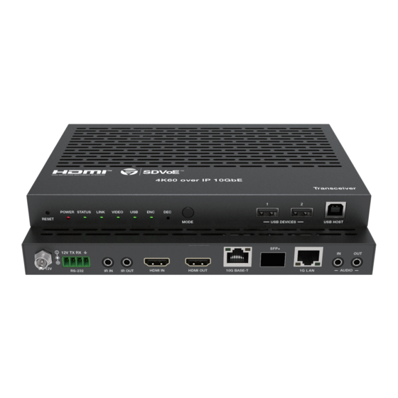
Page 6: Operation Controls And Functions
5. Operation Controls and Functions 5.1 Front Panel POWER STATUS LINK VIDEO RESET MODE USB DEVICES USB HOST Name Function Description Restore default settings button. Press and hold this button RESET button for 5 seconds in the power-on state to restore the default settings. -
Page 7: Rear Panel
5.2 Rear Panel SFP+ DC 12V HDMI IN HDMI OUT 10G BASE-T AUDIO RS-232 IR IN IR OUT Name Function Description DC 12V power input port. DC 12V Connect to PC or control system with a 4-pin phoenix connector cable for RS-232 signal pass-through or RS-232 firmware update. -
Page 8: Ir Pin Definition
5.3 IR Pin Definition IR RECEIVER IR BLASTER IR BLASTER IR RECEIVER Power 12V 6. Rack Mounting Instruction 6.1 5.5U Rack Mounting This transceiver can be mounted in a standard 5.5U rack (Please contact your supplier for 5.5U rack sale). The mounting steps are as follows: Step 1: Use included screws to fix two mounting ears on the transceiver, as shown in the figure below: 6 / 17... -
Page 9: Rack Mounting
Step 2: Insert the transceiver with mounting ears into a 5.5U rack (up to 10 units can be installed vertically), as shown in the figure below: Step 3: Use screws to fix mounting ears on the rack to complete the mounting, as shown in the figure below: 6.2 1U Rack Mounting This transceiver also can be mounted in a standard 1U rack (up to 4 units can... -
Page 10: Sdvoe System Control
Step 2: Fix two 1U rack panels on another two stacked transceivers in the same way, then use screws to fix two 1U rack panels together, as shown in the figure below: Step 3: Fasten screws between two 1U rack panels, so that four transceivers are mounted in a 1U rack, as shown in the figure below: 7. -
Page 11: Preview Stream Introduction
8. Preview Stream Introduction 8.1 Connecting Web for Control This transceiver supports playing video stream on computer via the corres- ponding software such as VLC media player, simultaneously you need to connect build-in Web GUI to control the video stream play. Default IP of the Web GUI is 169.254.3.1. - Page 12 Step 2: Set the PC’s IP address to the same network segment with Switch, for instance, set the IP address to be 169.254.3.30 and Subnet mask to be 255.255.0.0. Step 3: Enter the default IP address (169.254.3.1) of Web GUI into the web browser on PC.
- Page 13 Select the Username from the list and enter the password. The default passwords are: User Admin Username Password user admin After entering the password, click the “LOGIN” button and the following Status page will appear. Note: Status, Video, Network and Update pages are only accessible in Admin mode.
- Page 14 ■ Video Page The Video page allows you to set the Dectype coding (H264 / H265), resolution and bitrate for MainStream and SubStream. After setting, you need to reconnect to the video stream address. ■ Network Page The Network page allows the configuration of the network settings. Note that the IP Settings can be set only when the Mode button is set to Static.
-
Page 15: Vlc Media Player Instruction
■ Update Page This page is used to update the software of preview module, restore the factory default settings and reboot the preview module. 8.2 VLC Media Player Instruction After the Web GUI is successfully connected, open the VLC media player on PC. Please see the following icon. - Page 16 Click “Media > Open Network Stream” After clicking the “Open Network Stream” option, the following page will appear. 14 / 17...
- Page 17 Enter a MainStream or SubStream network URL, then click “Play” button. Stream Network URL MainStream rtsp://169.254.3.1/live/main/av_stream SubStream rtsp://169.254.3.1/live/sub/av_stream If you enter a MainStream network, please use the MainStream of Web GUI to set the Dectype, Resolution and Bitrate value of the VLC media player. At the same time, you can check the settings on VLC media player.
-
Page 18: Switch Mode
Choose “Tools>Codec information>Statistics” to check current Bitrate. Please see the following picture. Note that the Bitrate is floating up and down when you check it. This is a normal phenomenon. 9. Switch Mode The following Switch model is highly recommended. Manufacturer Model Number Netgear... -
Page 19: Application Example
10. Application Example Multi-viewer Transceiver (DEC Mode) Transceiver (ENC Mode) SFP+ SFP+ DC 12V DC 12V RS-232 IR IN IR OUT HDMI IN HDMI OUT 10G BASE-T AUDIO RS-232 IR IN IR OUT HDMI IN HDMI OUT 10G BASE-T AUDIO SFP+ DC 12V HDMI IN...
Need help?
Do you have a question about the iSwitch SDV-TR and is the answer not in the manual?
Questions and answers