Table of Contents
Advertisement
Quick Links
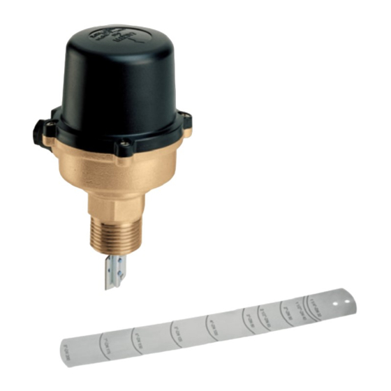
Uni-Switch™ Universal Flow Switch
© Copyright 2022 Caleffi
General Characteristics
A stainless steel bellows separates the electrical and hydronic sections, preventing the possibility
of contact of the fluid with the electrical components. Stainless steel is used in the construction
of many key parts, including the bellows, which protects the switch from corrosion. With a protection
classification of NEMA type 3 (IP54), the switch can be used in particularly humid and dusty
environments. The cover is made of a special non-combustible plastic material. The normally open
and normally closed contacts on the switch enable any electrical device to be switched on or off
as required at the operating flow rate. The operating point can be easily adjusted with the calibration screw.
Technical Characteristics
Connection size:
Maximum operating pressure:
Maximum temperature of the fluid:
Minimum temperature of the fluid:
Maximum ambient temperature:
Suitable for pipes:
Electrical Data
Max. Voltage:
Max. Current:
Electrical connection:
Protection class:
Certification Mark:
Function
The Caleffi Series 626 water flow switch detects the presence
or absence of flow in piping of heating, air conditioning, cooling
and water treatment systems as well as in pumping and process
systems. In heating systems, the flow switch is normally used to
shut off the burner of the boiler whenever there is no circulation
of the carrier fluid in the boiler circuit. A lack of circulation
can damage critical components and impair the operation of
temperature sensitive safety and protection devices.
This item is designed for use in closed hydronic systems. Do not
use in plumbing applications. This item does not meet the low-lead
plumbing standards of U.S. and Canada.
1
www.caleffi.com
626 Series
1" NPT male
150 psig (10 bar)
250° F (120° C)
-20° F (-30° C)
130° F (55° C)
1" to 8" (25 to 200mm)
½" NPT threaded with strain relief
NEMA type 3 (IP54)
68235.07
250 VAC
15A
Advertisement
Table of Contents

Subscribe to Our Youtube Channel
Related Manuals for CALEFFI Uni-Switch 626 Series


Summary of Contents for CALEFFI Uni-Switch 626 Series
- Page 1 68235.07 www.caleffi.com Uni-Switch™ Universal Flow Switch 626 Series © Copyright 2022 Caleffi Function The Caleffi Series 626 water flow switch detects the presence or absence of flow in piping of heating, air conditioning, cooling and water treatment systems as well as in pumping and process systems.
- Page 2 Failure to follow these instructions could result in property damage and/or personal injury. Caleffi shall not be liable for damages resulting from stress corrosion, misapplication or misuse of it products.
- Page 3 CONSIGNE DE SÉCURITÉ Ce symbole d'avertissement servira dans ce manuel à attirer l'attention sur la sécurité concernant instructions. Lorsqu'il est utilisé, ce symbole signifie. ATTENTION! DEVENEZ ALERTE ! VOTRE SÉCURITÉ EST EN JEU ! NE PAS SUIVRE CES INSTRUCTIONS PEUT PROVOQUER UN RISQUE DE SECURITE. AVERTISSEMENT: Ce produit peut vous exposer à...
- Page 4 Installation: To install the flow switch correctly follow these instructions: - When selecting the blade, identify the diameter of the pipe to which the appliance will be fitted; - The appliance comes pre-fitted with the 1” blade; - For diameters of 1 1/4” (DN 32) and above, the pre- fitted blade should be removed and the l ong blade fitted, cutting it to the correct corresponding size for the desired diameter;...
- Page 5 Electrical Connections: Unscrew the four cover screws and lift off the outer cover . CAUTION: Make sure the wires do not obstruct the function of the switch mechanism. AVERTISSEMENT: Assurez-vous que les fils ne sont pas entraver le fonctionnement de la changer le mécanisme.
- Page 6 Electrical Rating: Calibration: The minimum and maximum operating flow rates are given in the table below. Adjustments should be carried out as follows: turn the calibration screw (A) i n a clockwise direction f or the contacts to close at higher flow rate values or in a counterclockwise direction for lower flow rate values. When the adjustment has been made lock the screw (A) with the locking ring nut (B).
- Page 7 Operating flow rates: gpm (lpm)
- Page 8 NOTES Caleffi North America, Inc. 3883 West Milwaukee Road Milwaukee, WI 53208 12-2022 T: 414.238.2360 F: 414.238.2366...
Need help?
Do you have a question about the Uni-Switch 626 Series and is the answer not in the manual?
Questions and answers