Advertisement
Quick Links
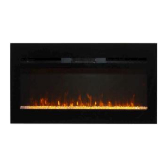
ELECTRIC FIREPLACE INSTRUCTION
MANUAL for models 221 149 222 150
IMPORTANT SAFETY INSTRUCTIONS
SAVE THESE INSTRUCTIONS FOR FUTURE USE
ATTENTION:
1. Find a location for the electric heater that is
WHEN USING ELECTRICAL APPLIANCES, BASIC PRECAUTIONS
SHOULD ALWAYS BE FOLLOWED TO REDUCE THE RISK OF FIRE,
protected from direct sunlight.
ELECTRIC SHOCK, AND INJURY TO PERSONS, INCLUDING THE
FOLLOWING:
2. Do not plug the electric heater into the power
outlet before you read all instructions.
www.cheminarte.com
Advertisement

Related Manuals for Chemin'Arte 221


Summary of Contents for Chemin'Arte 221
- Page 1 ELECTRIC FIREPLACE INSTRUCTION MANUAL for models 221 149 222 150 IMPORTANT SAFETY INSTRUCTIONS SAVE THESE INSTRUCTIONS FOR FUTURE USE ATTENTION: 1. Find a location for the electric heater that is WHEN USING ELECTRICAL APPLIANCES, BASIC PRECAUTIONS SHOULD ALWAYS BE FOLLOWED TO REDUCE THE RISK OF FIRE, protected from direct sunlight.
- Page 2 Read all instructions before using this heater. Failure to follow these important safety instructions may cause fire, electric shock or damage. Following proper safety and operating instructions is the responsibility of the owner. 1) This heater is hot when in use. To avoid burns, do not let skin come in direct contact with hot surfaces.
-
Page 3: Electrical Parameter
1875 watts, and 3-wire cord with grounding type plug and cord connector. 15) Do not plug this product into a receptacle controlled by a wall switch or dimmer. 16) Always use a certified electrician should new circuits or outlets be required. 17) Always disconnect power before performing any cleaning, maintenance or relocation of the heater. -
Page 4: Parts List
Parts list REF NO DESCRIPTION 4 PCS #8 x 1” 4 PCS 1 PC 4 PCS 2 PCS Installation: Caution: This heater can be installed in two ways, which can be selected according to your preference. Type 1. Built-in Wall Clearance: Please allow a minimum of 1,5cm spacing from the rear of the unit to a wall. - Page 5 Unit Overall Dimensions Model Cutout Dimensions(W*D*H) 122 x 15,30 x 45cm 112 x 15 x 43,20cm 149 / 222 152,5 x 15,30 x 45cm 140 x 15 x 43,20cm 183 x 15,30 x 45cm 180,40 x 15 x 43.20cm Step 1: (1)Find the two mounting screws and remove them. (2)Remove the front cover by pulling it upward (See Fig.
- Page 6 Fig. B Step 3:Replace the front cover and secure it with two mounting screws (See Fig. C). Fig. C Type 2. Wall Hanging Step 1: Select the wall location where you want to hang your electric heater. Draw a horizontal line using a level and mark 4 drill holes for the 4 anchor screws.
- Page 7 Step 2: Drill 4 holes 8 mm in diameter and 43 mm deep on the marked locations. For holes that do not hit stud, use the supplied wall anchor. Install the wall anchors into the holes and gently tap them into place with a hammer until the flange of the wall anchor is flush with the wall surface.
- Page 8 Fig.D(1) Fig. D(2) Step 5: Mount the heater on wall using the keyhole slots of the metal bracket at the back of the heater. See Fig. E. Make sure that the mounting bracket is completely engaged into the metal bracket at the back of the heater. Fig.
- Page 9 Fig. G 3-wire cable from power supply to 3-wire cable from heater Use the 3-wire cable from power supply where local codes permit connecting the frame-ground conductor to the neutral (white) junction box wire: A. 3-wire cable from power supply E.
- Page 10 The control panel is located right side of the heater. Control Panel LED Screen Remote Control : Press this button, the unit will enter standby mode. The indicator light will be on. Then you can select the following functions as desired. Press again to turn off the heater. : For modification time function - Press this button, the ‘SUN’...
- Page 11 NOTE: The date will be reset after power interrupt. : For automatic working time setting function - There are 10 time periods you can set to make the unit work automatically. Press this button, time serial number starts to twinkle. The ‘ON’ on the LED screen lights up.
-
Page 12: Maintenance
Fast Menu :Press the standby button and the heating button, the unit can heating immediately. Maintenance: WARNING: Completely disconnect power before attempting any maintenance or cleaning, to reduce the risk of fire or electric shock. Maintenance should only be performed by a certified technician. - Page 13 Information requirements for electric fixed local space heaters Model identifier(s): 150 149 222 221 Item Symbol Value unit Item unit Heat output Type of heat input, for electric storage local space heaters only (select one) Nominal heat manual heat charge control, with...
Need help?
Do you have a question about the 221 and is the answer not in the manual?
Questions and answers