Table of Contents
Advertisement
Quick Links
Advertisement
Table of Contents

Related Manuals for BUSCH SIMPLEX VO 0040 B


Summary of Contents for BUSCH SIMPLEX VO 0040 B
- Page 1 Operating instructions SIMPLEX Vacuum systems VO 0040 – 0080 B Dr.-Ing. K. Busch GmbH Schauinslandstraße 1, 79689 Maulburg Germany 0870S03254/-0000_en / Translation of the original operating instructions / Subject to change without notice 08.03.2021...
- Page 2 0870S03254_VO 0040-0080_B_-0000_IM_en 2 / 52...
-
Page 3: Table Of Contents
1 | Contents Contents Table of contents Contents ..................... 3 Table of contents ......................... 3 Register of tables ......................... 5 Register of illustrations ........................ 5 Safety ....................6 Safety devices ..........................6 Emergency information ....................... 6 Product description ................7 View vacuum system VO ...................... - Page 4 1 | Contents Maintenance ..................26 Maintenance plan ........................26 Check oil level ..........................27 Clean vacuum system from dust and dirt ................. 27 Oil change ..........................28 Changing of the air filter element ..................... 29 Check and clean suction strainer....................29 Troubleshooting ................
-
Page 5: Register Of Tables
1 | Contents Register of tables Tab. 1: Switching values ....................23 Tab. 2: Parameter settings (factory settings) ..............24 Tab. 3: Connections vacuum system VO 0040 B AAA G3XX ........37 Tab. 4: Connections vacuum system VO 0040 B AAA G3AX (mobile) ......38 Tab. -
Page 6: Safety
Before commissioning of the vacuum system, read these operating instructions with care. Please contact your contact person from Busch if there are any questions. Keep the operating instructions so that you can use them for reference at a later time if nec- essary. -
Page 7: Product Description
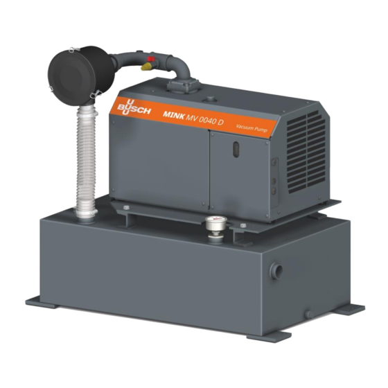
3 | Product description Product description View vacuum system VO Gas inlet Motor protection switch Gas outlet Air filter Claw-type vacuum pump MV Venting valve Name plate Pressure transmitter Vacuum gauge Vacuum vessel LED frequency converter Fig. 1: View vacuum system VO 0870S03254_VO 0040-0080_B_-0000_IM_en 7 / 52... -
Page 8: View Of The Claw-Type Vacuum Pump Mv
3 | Product description View of the claw-type vacuum pump MV Suction connection Cooling air outlet Gas outlet Frequency controlled drive Condensate drain Oil filler plug (oil dipstick) (aqua version) Oil drain plug Connection supply voltage (under the cover) Cooling air inlet Eye bolt Name plate Fig. -
Page 9: Function Principle
40 mbar. The permitted ambiance conditions can be found in the technical data (chap. 15). The vacuum system is designed for indoor use; for outdoor installation, contact Busch to make special arrangements if necessary. -
Page 10: Transport
4 | Transport Transport WARNING Danger of severe injury! Suspended load. • Never walk, stand or work below suspended loads. WARNING Hazard from vacuum system falling or tipping over! The weight of the vacuum system can kill a person or cause severe crushing. •... - Page 11 4 | Transport WARNING Danger of severe injury! Lift the vacuum system by devices of the individual components. • Do not lift the vacuum system by devices of the individual components, e.g. the vacuum pump, motor, etc. • Only lift the vacuum system as presented. Fig.
- Page 12 4 | Transport The vacuum pump can be lifted by the eye bolts. WARNING Danger of severe injury! Suspended load. • Never walk, stand and work below suspended loads! • The eye bolts (EB) must be in perfect condition and completely screwed into the machine and hand-tightened! •...
-
Page 13: Storage
5 | Storage Storage ATTENTION! Danger of damage to the vacuum pump drive! Long storage periods may cause capacitors in the drive to be weakened by electro-chemical condensation. In the most detrimental case, this may cause short-circuit and thereby destruc- tion of the drive. -
Page 14: Installation
6 | Installation Installation Installation Fig. 6: Installation environment • Ensure that the vacuum system is set up horizontally (deviation 1° max.) and anchor it in the ground with four bolts if necessary. • Technical data must be complied with. •... -
Page 15: Connection Lines/Pipes
In case of very long connection lines, it is recommended to use lines with larger cross-sections to avoid loss of efficiency. Please contact your contact person from Busch. 6.2.1 Gas inlet... -
Page 16: Gas Outlet
6 | Installation 6.2.2 Gas outlet • Connect the gas outlet line to the gas outlet openings of the vacuum pump if required. Di- mensions, see scale drawing in the appendix; connection size of thread: G 3/4“. • Ensure that the discharged gas can flow off unhindered. Never close the gas outlet line, do not throttle it and do not use it as a compressed air source. -
Page 17: Electrical Connection
6 | Installation Electrical connection DANGER Danger from electric shock! Electric shock will cause death or serious injury. • All live lines must be powered down before the electrical installation! • Before any electrical work, ensure that the vacuum pump is disconnected from the power supply and secured against accidental activation. - Page 18 6 | Installation • Ensure that the vacuum system is not impaired by electrical or electromagnetic impulses of the power supply. Contact Busch if necessary. • Connect the maintenance switch to the power supply (for connection values, see chap. 14).
-
Page 19: Start-Up
7 | Start-up Start-up Indication and control elements DANGER Danger from electric shock! Electric shock will cause death or serious injury. • Before commissioning, ensure that all electrical lines are covered and that the terminal box is closed! CAUTION Burn hazard! The surface of the vacuum pump may reach operating temperatures in excess of 70 °C in operation. -
Page 20: Indicators And Control Elements On The Motor Protection Switch
7 | Start-up 7.1.2 Indicators and control elements on the motor protection switch Fig. 9: Motor protection switch The vacuum system is switched on by way of the main switch at the motor protection switch (100Q1). The main switch has an undervoltage trigger for protection against residual voltage when using a pluggable power supply. -
Page 21: Dip Switches
7 | Start-up 7.1.5 DIP switches Fig. 11: DIP switch on the vacuum pump The DIP switches are used to make the following settings: DIP switches Description Standard No function 0 = Analog input 2 operates in current mode (4 – 20 mA) 1 = Analog input 2 operates in voltage mode (2 –... -
Page 22: Manual Operating Unit (Option)
7 | Start-up 7.1.6 Manual operating unit (option) Display and operating elements on the manual operating unit The vacuum system VO can be optionally operated via the manual operating unit (see sepa- rate instructions parameter description 0870 166 596) Go back in the menu; Exit edit mode;... -
Page 23: Measuring And Control Facilities And Settings
7 | Start-up Connection of the manual operating unit to vacuum pump DANGER Danger from electric shock! Electric shock will cause death or serious injury. • Before any electrical work, ensure that the vacuum pump is disconnected from the power supply and secured against accidental activation. -
Page 24: Parameter Settings
7 | Start-up 7.1.8 Parameter settings The parameters are set on the manual operating unit. Parameter Description Set to Measuring margin of the pressure transmitter P3.7 100 % = 0 ... 1,000 mbar 100% 50 % = 0 ... 500 mbar 10 % = 0 ... -
Page 25: Operation
7 | Start-up Operation ATTENTION! Danger of damage to the vacuum pump. Frequent starting/stopping by switching the power supply on/off. Starting the vacuum pump by switching the power supply on/off is permitted at most once per minute (max. 60 x hour). At least 10 seconds must pass between switching off and on again. -
Page 26: Maintenance
• Check the suction strainer (IS, chap. 0) and clean it if necessary. • Perform a general overhaul of the vacuum pump (in- Every 6 years form Busch). Switch and control cabinet • Check the parts in contact with the medium for Every 8000 hrs. or, at the... -
Page 27: Check Oil Level
8 | Maintenance Check oil level Proceed as follows: • Switch off the vacuum system. • Wait 1 minute after switching off the vacuum pumps, before checking the oil level. The oil level should be constant over the entire service life. If the oil level drops, the gear box is leaking and the vacuum pump needs to be repaired. -
Page 28: Oil Change
ATTENTION! Operation of the vacuum pump without oil will cause severe damage to it quickly. • Only use oils approved by Busch. For information to the oil type and oil volume, see the technical data (chap. 15) and oil (chap. 16). -
Page 29: Changing Of The Air Filter Element
• Open the quick clamps and remove the filter insert • Insert a new filter. Original spare part from Busch: Parts no. 0532 000 003 Check and clean suction strainer A suction strainer is installed in the gas inlet to protect the vacuum pump. -
Page 30: Troubleshooting
9 | Troubleshooting Troubleshooting DANGER Danger from electric shock! Electric shock will cause death or serious injury. • Before any electrical work, ensure that the vacuum pump is disconnected from the power supply and secured against accidental activation. Wait for another 60 seconds after the LED displays switch off. -
Page 31: Fault Messages At The Manual Operating Unit
• Top up oil. The oil level is too low To solve any problems that are not listed in the section on troubleshooting, talk to your Busch contact. Fault messages at the manual operating unit If one or several errors occur, the name of the error will start to flashing in the display. -
Page 32: Resetting Error
9 | Troubleshooting Resetting error CAUTION Danger due to accidental starting of the vacuum pump! The vacuum pump may start up independently after error reset. Make sure that starting the vacuum pump does not lead to a dangerous situation. An error is signaled when the LED “FLT” lights up (see LED display (fig. -
Page 33: Spare Parts And Accessories
Measuring range -1 – 0 bar 0545 000 002 If further spare parts are required, ask your Busch contact for the detailed spare parts list. The list of Busch companies around the world (at the time these operating instructions are is- sued) can be found on the reverse. -
Page 34: Field Bus Option Card
10 | Spare parts and accessories 10.2.3 Field bus option card The vacuum pump can be retrofitted using field bus option cards with different bus systems. Also consult your Busch branch. 0870S03254_VO 0040-0080_B_-0000_IM_en 34 / 52... -
Page 35: Repair
• Decontaminate the vacuum pump and indicate the contamination status based on a "Con- formation declaration". Busch accepts only vacuum pumps that include a completed and legally signed "Contamina- tion declaration". The form can be downloaded from www.buschvacuum.com. -
Page 36: Decommissioning And Disposal
12 | Decommissioning and disposal 12 Decommissioning and disposal 12.1 Stop operating vacuum system • Disconnect the vacuum system from the power supply. • Vent all connected pipes to atmospheric pressure. • Disconnect all connections. If the vacuum system has to be stocked, observe following: •... -
Page 37: Dimensions Sheets
13 | Dimensions sheets 13 Dimensions sheets Dimensions vacuum system VO 0040 B AAA G3XX Fig. 20: Dimensions vacuum system VO 0040 B AAA G3XX Center of Lifting point gravity Pos. Designation Connection Standard Gas inlet G 1 1/4“, female thread ISO 228-1 Gas outlet G 3/4", female thread... - Page 38 13 | Dimensions sheets Dimensions vacuum system VO 0040 B AAA G3AX (mobile) Fig. 21: Dimensions vacuum system VO 0040 B AAA G3AX (mobile) Center of gravity Pos. Designation Connection Standard Gas inlet G 1 1/4“, female thread ISO 228-1 Gas outlet G 3/4", female thread ISO 228-1...
- Page 39 13 | Dimensions sheets Dimensions vacuum system VO 0060 B AAA H3XX Fig. 22: Dimensions vacuum system VO 0060 B AAA H3XX Center of Lifting point gravity Pos. Designation Connection Standard Gas inlet G 1 1/4“, female thread ISO 228-1 Gas outlet G 3/4", female thread ISO 228-1...
- Page 40 13 | Dimensions sheets Dimensions vacuum system VO 0060 B AAA H3AX (mobile) Fig. 23: Dimensions vacuum system VO 0060 B AAA H3AX (mobile) Center of gravity Pos. Designation Connection Standard Gas inlet G 1 1/4“, female thread ISO 228-1 Gas outlet G 3/4", female thread ISO 228-1...
- Page 41 13 | Dimensions sheets Dimensions vacuum system VO 0080 B AAA I3XX Fig. 24: Dimensions vacuum system VO 0080 B AAA I3XX Center of Lifting point gravity Pos. Designation Connection Standard Gas inlet G 1 1/4“, female thread ISO 228-1 Gas outlet G 3/4", female thread ISO 228-1...
- Page 42 13 | Dimensions sheets Dimensions vacuum system VO 0080 B AAA I3XX(mobile) Fig. 25: Dimensions vacuum system VO 0080 B AAA I3XX(mobile) Center of gravity Pos. Designation Connection Standard Gas inlet G 1 1/4“, female thread ISO 228-1 Gas outlet G 3/4", female thread ISO 228-1 Venting valve...
-
Page 43: Connecting Values Of The Vacuum System Vo
14 | Connecting values of the vacuum system VO 14 Connecting values of the vacuum system VO 14.1 Connection values Vacuum system type VO 0040 B 3 x 380 - 415 V AC / PE 50 Hz 1.3 kW 4.4 A 16 A VO 0060 B 3 x 380 - 415 V AC / PE... -
Page 44: Circuit Diagram Vacuum Systems Vo
14 | Connecting values of the vacuum system VO 14.2 Circuit diagram vacuum systems VO Fig. 26: Circuit diagram vacuum systems VO 0870S03254_VO 0040-0080_B_-0000_IM_en 44 / 52... -
Page 45: Circuit Diagram Of The Claw Vacuum Pump Mv 0040 D / Mv 0060 D / Mv 0080 D, 3 Phase
14 | Connecting values of the vacuum system VO 14.3 Circuit diagram of the claw vacuum pump MV 0040 D / MV 0060 D / MV 0080 D, 3 phase Fig. 27: Circuit diagram MV 0040 D / MV 0060 D / MV 0080 D, 3 phase 0870S03254_VO 0040-0080_B_-0000_IM_en 45 / 52... -
Page 46: Electrical Data Of The Terminals Of The Control Unit
Digital input 5 Free to use Digital input 4 Reset maintenance counter Mass digital output Mass Busch pressure transmitter Analog input 2 4 … 20 mA 0 … 1 bar abs. Digital input 3 Reset failure Opened = rotation speed control... -
Page 47: Technical Data
15 | Technical data 15 Technical data Unit VO 0040 B VO 0060 B VO 0080 B Rated intake capacity (50/60 Hz) m³/h Final pressure hPa (mbar) abs. Rated output of motor (50 / 60 Hz) (motor and fan wheel) Motor nominal rotation speed 1200 …... -
Page 48: Gear Oil
16 | Gear oil 16 Gear oil VSB 100 ISO-VG Oil type Synthetic oil Part number 1 l packaging 0831 168 351 Part number 5 l packaging 0831 168 352 Tab. 12: Gear oil Check the name plate (NP, fig. 2) to see which oil the vacuum pump was filled with. 0870S03254_VO 0040-0080_B_-0000_IM_en 48 / 52... -
Page 49: Eu Declaration Of Conformity
This EU declaration of conformity and the CE marking on the name plate apply to the machine in the scope of the delivery by Busch. The manufacturer is solely responsible for issuing this declaration of conformity. If the machine is integrated into a higher-level machine system, the manufacturer of this system (if applicable, the com- pany operating the system) must issue a declaration of conformity for the higher-level machine or system and affix the CE marking. - Page 50 0870S03254_VO 0040-0080_B_-0000_IM_en 50 / 52...
- Page 51 Notes...
- Page 52 Portugal United Arab Emirates Chile service_sales@busch.co.il busch@busch.pt sales@busch.ae info@busch.cl Italy Romania United Kingdom China info@busch.it office@buschromania.ro sales@busch.co.uk info@busch-china.com Japan Russia Colombia info@busch.co.jp info@busch.ru info@buschusa.com info@buschvacuum.co Korea Singapore Czech Republic busch@busch.co.kr sales@busch.com.sg info@buschvacuum.cz 0870S03254/-0000_en / © Dr.-Ing. K. Busch GmbH www.buschvacuum.com...
Need help?
Do you have a question about the SIMPLEX VO 0040 B and is the answer not in the manual?
Questions and answers