Advertisement
Table of Contents
The JB-111N BUS signal PG output module
The JB-111N is a component of the JABLOTRON 100+ system.
It provides an output relay switch. It can be used for
switching on/off the lights, ventilators, etc. The relay can
be controlled with a programmable control panel (PG) output
or according to the status of a section (set = relay on) or when
there is an alarm in a chosen section (alarm = relay on). The device
should be installed by a trained technician with a valid certificate
issued by an authorized distributor.
Installation
The module can be installed into the JA-19xPL mounting box
(by Jablotron) or into the control panel box. In order to comply with
the security grade 2 classification, the module must be installed into
the JA-194PL or JA-195PL mounting box together with the JA-111H
TRB module.
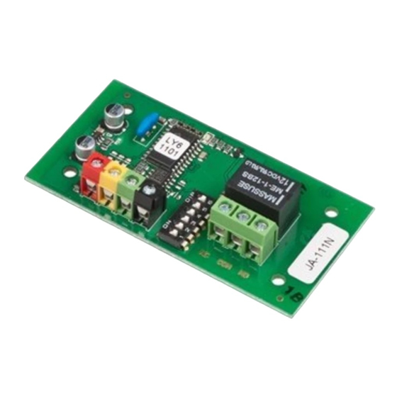
Figure: 1 – BUS terminals; 2 – red relay switching indicator;
3 – configuration switch; 4 – output relay; 5 – relay terminals
1. Use the switch (3) to set the required number of the PG output
or the number of the section to which the relay should react
(see tables).
2. Connect BUS wires to the terminals (1).
When connecting the module to the system
BUS, always switch the power off.
If the module is installed outside the protected
area, the JA-110T BUS insulator should be used
for the external section of the wiring.
The
output
an overload protection.
3. Switch on the system and test its functioning
4. Check the supply voltage at the BUS terminals (red, black)
when the relay is activated. The voltage must be at least 9V.
5. Connect the controlled device to the relay output terminals (5).
Notes:
The module does not occupy any position in the control panel
(it is not enrolled into the system).
If
you
enroll
multiple
to the system, they will have the same reaction.
The number of modules is only limited by the power
consumption from the BUS.
The setting of individual programmable outputs is done
in the PG outputs window in the F-Link software. A detailed
description of the setting is available in the control panel
installation manual.
If the output reacts to a setting of a section, it is triggered when
the selected section is fully set.
If the output reacts to an alarm, it is triggered when there
is external or internal warning (EW or IW).
The JB-111N BUS signal PG output module
contact
does
not
contain
modules
with
identical
settings
N
ON
PG
1
1
2 3 4 5 6 7
8
1 2 3 4
5 6 7 8
O N
ON
PG
2
1
2 3 4 5 6 7
8
1 2 3 4
5 6 7 8
O N
ON
PG
3
1
2 3 4 5 6 7
8
1 2 3 4
5 6 7 8
O N
ON
PG
4
1
2 3 4 5 6 7
8
1 2 3 4
5 6 7 8
O N
ON
PG
5
1
2 3 4 5 6 7
8
1 2 3 4
5 6 7 8
O N
ON
PG
6
1
2 3 4 5 6 7
8
1 2 3 4
5 6 7 8
O N
ON
PG
7
1
2 3 4 5 6 7
8
1 2 3 4
5 6 7 8
O N
ON
PG
8
1
2 3 4 5 6 7
8
1 2 3 4
5 6 7 8
N
ON
PG
33
1
2 3 4 5 6 7
8
1 2 3 4
5 6 7 8
O N
ON
PG
34
1
2 3 4 5 6 7
8
1 2 3 4
5 6 7 8
O N
ON
PG
35
1
2 3 4 5 6 7
8
1 2 3 4
5 6 7 8
O N
ON
PG
36
1
2 3 4 5 6 7
8
1 2 3 4
5 6 7 8
O N
ON
PG
37
1
2 3 4 5 6 7
8
1 2 3 4
5 6 7 8
O N
ON
PG
38
1
2 3 4 5 6 7
8
1 2 3 4
5 6 7 8
O N
ON
PG
39
1
2 3 4 5 6 7
8
1 2 3 4
5 6 7 8
O N
ON
PG
40
1
2 3 4 5 6 7
8
1 2 3 4
5 6 7 8
N
ON
PG
65
1
2 3 4 5 6 7
8
1 2 3 4
5 6 7 8
O N
ON
PG
66
1
2 3 4 5 6 7
8
1 2 3 4
5 6 7 8
O N
ON
PG
67
1
2 3 4 5 6 7
8
1 2 3 4
5 6 7 8
O N
ON
PG
68
1
2 3 4 5 6 7
8
1 2 3 4
5 6 7 8
O N
ON
PG
69
1
2 3 4 5 6 7
8
1 2 3 4
5 6 7 8
O N
ON
PG
70
1
2 3 4 5 6 7
8
1 2 3 4
5 6 7 8
O N
ON
PG
71
1
2 3 4 5 6 7
8
1 2 3 4
5 6 7 8
O N
ON
PG
72
1
2 3 4 5 6 7
8
1 2 3 4
5 6 7 8
N
ON
PG
97
1
2 3 4 5 6 7
8
1 2 3 4
5 6 7 8
O N
ON
PG
98
1
2 3 4 5 6 7
8
1 2 3 4
5 6 7 8
O N
ON
PG
99
1
2 3 4 5 6 7
8
1 2 3 4
5 6 7 8
O N
ON
PG
100
1
2 3 4 5 6 7
8
1 2 3 4
5 6 7 8
O N
ON
PG
101
1
2 3 4 5 6 7
8
1 2 3 4
5 6 7 8
O N
ON
PG
102
1
2 3 4 5 6 7
8
1 2 3 4
5 6 7 8
O N
ON
PG
103
1
2 3 4 5 6 7
8
1 2 3 4
5 6 7 8
O N
ON
PG
104
1
2 3 4 5 6 7
8
1 2 3 4
5 6 7 8
Table 1: The output reacts to the PG output state.
1 / 2
O N
ON
PG
PG
9
17
1
2 3 4 5 6 7
8
1 2 3 4
5 6 7 8
O N
ON
PG
PG
10
18
1
2 3 4 5 6 7
8
1 2 3 4
5 6 7 8
O N
ON
PG
PG
11
19
1
2 3 4 5 6 7
8
1 2 3 4
5 6 7 8
O N
ON
PG
PG
12
20
1
2 3 4 5 6 7
8
1 2 3 4
5 6 7 8
O N
ON
PG
PG
13
21
1
2 3 4 5 6 7
8
1 2 3 4
5 6 7 8
O N
ON
PG
PG
14
22
1
2 3 4 5 6 7
8
1 2 3 4
5 6 7 8
O N
ON
PG
PG
15
23
1
2 3 4 5 6 7
8
1 2 3 4
5 6 7 8
O N
ON
PG
PG
16
24
1
2 3 4 5 6 7
8
1 2 3 4
5 6 7 8
O N
ON
PG
PG
41
49
1
2 3 4 5 6 7
8
1 2 3 4
5 6 7 8
O N
ON
PG
PG
42
50
1
2 3 4 5 6 7
8
1 2 3 4
5 6 7 8
O N
ON
PG
PG
43
51
1
2 3 4 5 6 7
8
1 2 3 4
5 6 7 8
O N
ON
PG
PG
44
52
1
2 3 4 5 6 7
8
1 2 3 4
5 6 7 8
O N
ON
PG
PG
45
53
1
2 3 4 5 6 7
8
1 2 3 4
5 6 7 8
O N
ON
PG
PG
46
54
1
2 3 4 5 6 7
8
1 2 3 4
5 6 7 8
O N
ON
PG
PG
47
55
1
2 3 4 5 6 7
8
1 2 3 4
5 6 7 8
O N
ON
PG
PG
48
56
1
2 3 4 5 6 7
8
1 2 3 4
5 6 7 8
O N
ON
PG
PG
73
81
1
2 3 4 5 6 7
8
1 2 3 4
5 6 7 8
O N
ON
PG
PG
74
82
1
2 3 4 5 6 7
8
1 2 3 4
5 6 7 8
O N
ON
PG
PG
75
83
1
2 3 4 5 6 7
8
1 2 3 4
5 6 7 8
O N
ON
PG
PG
76
84
1
2 3 4 5 6 7
8
1 2 3 4
5 6 7 8
O N
ON
PG
PG
77
85
1
2 3 4 5 6 7
8
1 2 3 4
5 6 7 8
O N
ON
PG
PG
78
86
1
2 3 4 5 6 7
8
1 2 3 4
5 6 7 8
O N
ON
PG
PG
79
87
1
2 3 4 5 6 7
8
1 2 3 4
5 6 7 8
O N
ON
PG
PG
80
88
1
2 3 4 5 6 7
8
1 2 3 4
5 6 7 8
O N
ON
PG
PG
105
113
1
2 3 4 5 6 7
8
1 2 3 4
5 6 7 8
O N
ON
PG
PG
106
114
1
2 3 4 5 6 7
8
1 2 3 4
5 6 7 8
O N
ON
PG
PG
107
115
1
2 3 4 5 6 7
8
1 2 3 4
5 6 7 8
O N
ON
PG
PG
108
116
1
2 3 4 5 6 7
8
1 2 3 4
5 6 7 8
O N
ON
PG
PG
109
117
1
2 3 4 5 6 7
8
1 2 3 4
5 6 7 8
O N
ON
PG
PG
110
118
1
2 3 4 5 6 7
8
1 2 3 4
5 6 7 8
O N
ON
PG
PG
111
119
1
2 3 4 5 6 7
8
1 2 3 4
5 6 7 8
O N
ON
PG
PG
112
120
1
2 3 4 5 6 7
8
1 2 3 4
5 6 7 8
MLY22101
PG
25
PG
26
PG
27
PG
28
PG
29
PG
30
PG
31
PG
32
PG
57
PG
58
PG
59
PG
60
PG
61
PG
62
PG
63
PG
64
PG
89
PG
90
PG
91
PG
92
PG
93
PG
94
PG
95
PG
96
PG
121
PG
122
PG
123
PG
124
PG
125
PG
126
PG
127
PG
128
Advertisement
Table of Contents

Related Manuals for jablotron JB-111N


Summary of Contents for jablotron JB-111N
- Page 1 1 2 3 4 5 6 7 8 The module can be installed into the JA-19xPL mounting box (by Jablotron) or into the control panel box. In order to comply with 2 3 4 5 6 7 1 2 3 4...
- Page 2 Table 3: The relay reacts to setting the chosen section to an alarm in the chosen section JABLOTRON ALARMS a.s. hereby declares that the JB-111N is in a compliance with the relevant Union harmonisation legislation: Directives No: 2014/30/EU, 2011/65/EU, when used as intended.
Need help?
Do you have a question about the JB-111N and is the answer not in the manual?
Questions and answers