Advertisement
Quick Links
Advertisement

Related Manuals for Barberan PUR-33-L

Summary of Contents for Barberan PUR-33-L
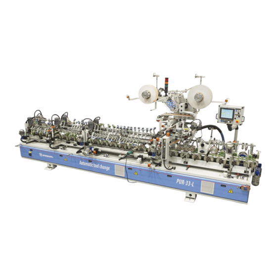
- Page 1 MACHINE Mod.: PUR-33-L MACHINE Nº.: 18248 CUSTOMER : BAHRAIN ALUMINUN KITCHEN...
- Page 2 INDEX 0. General warnings 1. Instructions before use 1.1 Machine description 1.2 Composition and parts 1.2.1 Main elements 1.2.2 Secondary elements 1.3 Preparation before use - Installation 1.3.1 Forwarding and reception 1.3.2 Manipulation procedure 1.3.3 Positioning and installation 1.3.3.1 Positioning conditions 1.3.3.2 Electric connections 1.3.3.3...
- Page 3 4.4 Electric schemes 5. Remarks and attachments 5.1 Safety symbology 5.1.1 Forbidding signals 5.1.2 Warming signals 5.1.3 Obligation signals 5.2 Acoustic pollution 5.3 Warnings about the products...
- Page 4 0. General warnings • Before the machine is set in operation, the user must read very carefully the content of this manual so that he gets a deep knowledge about the technical features and operation of this machine. • Do not permit that non-allowed personnel make any operation or repairing works on the machine.
-
Page 5: Instructions Before Use
1. Instructions before use • Before the machine is set in operation, the user must read very carefully the content of this manual so that he gets a deep knowledge about the technical features and operation of this machine. Machine description. Machine designed for the gluing and application of rolled material on profiles, made of MDF, particleboard, low quality wood, etc. - Page 7 1.3.1 Forwarding and reception The selection of the different transport ways depends on the geographic location of the customer in relation to Barberan, S.A. Upon arrival of the machine it must be checked that no element has been damaged during the transport.
- Page 8 Warnings • Keep the operation zone free. Consider it a security zone. This zone will be free of persons and objects that could be an obstacle by shifting the machine or moving any of its parts. Take care that the raising elements do not encounter an obstacle in their way.
- Page 9 The power oscillations must not be higher than 10%, otherwise they would cause damages in the electric equipment of the machine. It is completely obligatory the connection to earth of the main power source of the machine. Use the earth connection marked as PE in the electric cabinet.
- Page 10 The air speed inside the installation should be at least 25 m/s. BARBERAN, S. A. WILL NOT BE LIABLE FOR ANY INJURIES OR DAMAGES IN THE MACHINE CAUSED BY THE BREACH OF GUIDELINES STATED IN THIS MANUAL.
- Page 11 2. Operation for commissioning and safety 2.1 Controls 2.2 ADJUSTMENT PARAMETERS ( user’s tactile terminal) INTRODUCTION The functioning and adjustment parameters of the machine are done through the user’s tactile terminal, connected to the control of the machine. This tactile terminal allows the display of the functioning parameters of the machine (working speed, production data, etc.), and also the selection and adjustment of the functioning of the machine.
- Page 12 A pop up window is opened directly on the screen. These screens can be opened or closed by using a switch, tactile push button, etc. The pop up windows are composed by three items: folders, groups and panels. It is also possible to open a pop up key board to introduce data.
- Page 13 “MANUAL Selection button”. Image of an AUT/MAN button, when the related parameter is in MANUAL mode. Hereafter, we will describe the different handling of the machine that have to be controlled from the tactile terminal, including tactile buttons, parameters, data to be modified, etc.
- Page 14 − Lamps. The window that pops up with this button, allows to switch on or off the lamps. − Leisters. The window that pops up with this button, allows to switch on or off the leisters. − Brushes. The window that pops up with this button, allows to switch on or off the brushes.
- Page 15 NOZZLE HEAD The machine has a nozzle head for glue application on the foil. The head has two electrovalves: one for the opening and glue feeding and the other for the approach, so that the nozzle approaches to the foil. At the moment that the electrovalve for the nozzle opening is set on, the control sends automatically a signal to the premelter so that the pump starts and sends glue.
- Page 16 GRAMMAGE CONTROL This system allows the automatic adjustment of the glue dosing with the nozzle, thanks to the speed adjustment of the premelter pump. The pump of the premelter equipment works within a margin of 0 to 100 r.p.m. For its command, the control gives an analogical speed signal from 0 to 10 Volts.
- Page 17 4. Manual speed. Turning speed of the pump when manual mode is selected. 5. By touching on this button, you will be able to go to the rest of the parameters of pump information. 1. Glue density. Given in grs/cm .
- Page 18 Moreover, the lamps have a preheating function. This function consists of the start-up of the lamps with the push-button LAMPS MANUAL. Once this button is pushed, if the lamps are activated, these will start-up and stop automatically after two seconds. Bear in mind that if, during those two seconds, a workpiece would be introduced in the machine, the preheating function would be cancelled and the lamps would stop due to the encoder impulse counter.
-
Page 19: Production Data
1. Close the popped up screen. 2. Selector ON / OFF leisters. 3. Impulse number counted by the machine until the leisters stop, once the leisters have started up and the photoelectric cell does not have any entry signal of the machine. BRUSHES The brush functioning selection is done through a popped up screen. - Page 20 If, for any reason, it would be necessary to modify some of those data, you should first contact the Technical Service of BARBERAN S.A. − Maximum line speed: Maximum value of the speed of the line.
- Page 21 2.2 Comissioning and checking. After doing all the connection operations, check the arrival of tensión to the machine. Turn the “main switch” to ON position and activate the pusher “activated controls” placed at the control board. Warning • Check if the motors turn in the correct sense. 2.3 Workpiece adjustments 2.3.1.- Adjustment of the transport wheels and the tools.
- Page 22 • The improper performance of the adjustment does not asure the correct operation of the machine. • BARBERAN, S.A. does not guarantee the correct operation of the machine in case of improper adjustment of the parts.
- Page 23 2.4 Product adjustments 2.4.1.- WIDTH ADJUSTABLE SLOT NOZZLE HEAD 330 mm 2.4.1.1.DESCRIPTION 1. Glue input and hose connection. 2. Heating element. 3. Regulation gauge. 4. Activation and position indicator of the left gauge 5. Activation and position indicator of the left gauge 6.
- Page 24 2.4.1.2.TECHNICAL FEATURES. • Minimum application width: 25 mm. (centered) • Maximum application width: 330 mm. • Heating element power: 1000 W 2.4.1.3.ADJUSTING THE APPLICATION WIDTH. The adjustment of the application width is done turning the screw of the left gauge (04) and the right gauge (05) using a tool. The sum of the two numbers in their respective position indicators will be the application width.
- Page 25 2.4.1.4.MAINTENANCE 2.4.1.4.1. Daily tasks. 2.4.1.4.1.1.- Steps to follow by switching on the wrapping machine. • Heat up the slot nozzle until it reaches the working temperature. • Using a gauge sheet of 0.4 mm thickness, clean the slot (13) shifting the sheet softly taking care not to damage the gauges nor the slot.
- Page 26 2.4.1.4.1.2. Operation to be performed when you stop the wrapping machine. • Once the glue flow is closed, keep the slot nozzle heated at the working temperature. • Using a gauge sheet of 0,4 mm, clean the slot (13) shifting the sheet softly so that you do not damage accidentally the gauges nor the slot.
- Page 27 2.4.1.4.2.Weekly maintenance. 2.4.1.4.2.1. Operations to do when you stop the wrapping machine. 17 18 19 20 21 • Remove the filter cover (17) from the head housing (07) using a key tool. • Remove the used filter (21) .
- Page 28 • Install a second clean filter, changing the joints (18) in case they are damaged. • Clean the used filter and let him one week long submerged in solvent. DO NOT CLEAN THE JOINTS WITH SOLVENT 2.4.1.5. DISASSEMBLING AND CLEANING OF THE HEAD INSIDE. THE SLOT NOZZLE APPLICATOR IS A FRAGILE MECHANISM AND THERFORE IS IT RECOMMENDABLE TO PROCEED CAREFULLY WHILE DISASSEMBLING THE HEAD AS IT COULD BE DAMAGED AND CAUSE GLUE...
- Page 29 • Using the bolts placed at the side of the centring pins (12), remove the upper cover of the head (08) and place it so that your can see the inner structure over a surface that does not damage it. DURING THIS OPERATION YOU HAVE TO TAKE CARE SPECIALLY NOT TO HIT OR SCRATCH THE ZONES OF THE HEAD WHERE THE GAUGES RUN, AS WELL AS THE END OF THEM AS THIS CAN CAUSE...
- Page 30 • Clean the gauges the limit the application with a wipe and solvent. • Scrape with a metallic piece the glue rests, taking care not to scratch the metallic structure. DURING THIS OPERATION YOU HAVE TO TAKE CARE SPECIALLY NOT TO HIT OR SCRATCH THESE ZONES AS THIS CAN CAUSE IRREGULARITIES IN THE APPLICATION.
- Page 31 • Clean the metallic surfaces with a wipe and solvent, specially the zones of the head (23 and 24) where the gauges move along. • Place the joint again ( 38 ) and assemble the head. The cleaning process has finished.
- Page 32 2.4.1.6. CHANGING THE WIDTH ADJUSTMENT GAUGES. In case of gauge breakdown, please proceed as follows: • Proceed to disassemble and clean the head as indicated in the prior section, taking the same precautions. • With the head disassembled and clean, remove the metallic washer (25) and the one made of teflon (26).
- Page 33 1. Remove the filter as per instructions in point 4.2.1 . 2. Being helped by a thin bar M12, remove the bushing (35). 3. Remove the toric joints (c) . 4. Remove the assembly for glue open-close (32): 5. Lose the cover (33) and remove the shaft (34). 6.
- Page 34 • Marks in the application: Clean with solvent the contact zone of the slot nozzle with the foil and proceed as in the prior point. If the problem persists, clean the inside of the head as explained in point 5. Check if the glue has been microfiltered.
-
Page 35: Maintenance
3. Maintenance 3.1. Preventive Machine part Activity Periodicity You must do a visual checking of these components and Emergency stop and limit verify its operation by performing emergency stops and switch for doors and Weekly proceed to replace them if they have strokes, leaks or in housings case of malfunction. - Page 36 Warning • Not paying attention to the daily maintenance instructions can cause personal and material damages, as well as premature wearing of the elements described in the table. 3.2 . Periodical maintenance Warning • The periodical maintenance operations must be exclusively performed by qualified personnel and following the instructions described in this manual.
- Page 37 d) High temperature chains (up to 150º C)(*) - HOTEMP 2000 SPRAY KLÜBER - SIL GREASE ARS DILUBE e) High temperature chains (up to 250º C) (** ) - Q8 BERNOULLI S280 Q8 OILS f) High temperature chains (more than 250º C) (** ) - NEVER-SEER REGULAR GRADE BOSTIK g) Bearings and bearing supports (*)
- Page 38 • BARBERAN, S.A. will not be responsible when products are used that are not suitable for these operations (cleaning, greasing, etc.).
- Page 39 4. Technical features, drawings and schemes 4.1 Technical features...
- Page 40 4.2 Drawings...
- Page 47 IMPREGNATION STATION 18248 / 5 TUBE Cod.: 8.023 Cod.: 222.399 Cod.: 222.398...
- Page 48 IMPREGNATION STATION 18248 / 5 Cod.: 103.879 Cod.: 223.710 Cod.: 248.742 Cod.: 5.432 Cod.: 6.849 Cod.: 248.742 Cod.: 248.743 Cod.: 253.603...
- Page 67 BLOW CLEANING UNIT 18248 / 16 Cod.: 7.562 Cod.: 114.646 Cod.: 114.647 (Pieces ) Cod.: 114.648...
- Page 68 TURBINE 18248 / 17 Cod.: 269.341 Cod.: 313.453 Cod.: 182.059 Cod.: 270.732 Cod.: 46.930...
- Page 69 18248 / 18 POWER PACKS AND IONIZING BAR Cod.: 381.232 Cod.: 384.743...
- Page 70 SAFETY LIMIT SWITCHES 18248 / 20 Cod.: 193.068 LIMIT SWITCH FOR STOPPING THE MACHINE IN CASE OF EMERG...
- Page 71 4.3 Pneumatic schemes...
- Page 73 4.4 Electric schemes...
- Page 84 Ω Ω...
- Page 102 5. Remarks and attachments 5.1 Safety symbology 5.1.1 Prohibition signals ACCESS PROHIBITED. DANGER TO BE CAUGHT BY THE ROLLERS ACCESS PROHIBITED. DANGER THAT HANGING ELEMENTS ARE CAUGHT BY THE ROLLERS HEAT FOCUSES PROHIBITED DUE TO EXPLOSION OR FIRE RISK ACCESS PROHIBITED TO MACHINE PARTS IN MOTION.
- Page 103 5.1.2 Warning signals ATTENTION. BURN RISK BY CONTACT ATTENTION. ELECTRIC SHOCK RISK ATTENTION. RISK OF CUTS OR AMPUTATIONS OF BODY PARTS. ATTENTION. RISK OF CUTS OR AMPUTATIONS OF BODY PARTS. ATTENTION. HANDS CAN BE GRABBED BY THE ROLLERS. ATTENTION. HANDS CAN BE GRABBED.
- Page 104 ATTENTION GRAB RISK IN CONVEYORS ATTENTION. INFLAMMABLE PRODUCTS WARNING: Not paying attention could cause personal injuries, dead or material damages. WARNING: Machine in operation. WARNING: Risk to suffer electric shocks. WARNING: Hand grabbing risk.
- Page 105 WARNING: Grab risk through machine in operation. 5.1.3. Obligation signals Obligación de utilizar gafas protectoras Obligación de utilizar guantes Obligación de utilizar calzado protector Obligación de utilizar cascos protectores del ruido 5.2 Acoustic pollution The measurements of the noise emission have been performed adapting to the present standards, therefore it is not a risk to take into consideration.