Table of Contents
Advertisement
Advertisement
Table of Contents

Related Manuals for Messersi TC50

Summary of Contents for Messersi TC50
- Page 1 USE – MAINTENANCE 03672833 MINI TRANSPORTER TC50 TC50/AV ______________...
-
Page 2: Table Of Contents
CONTENTS 1. GENERAL ACCIDENT PREVENTION ............3 2. MAIN CHARACTERISTICS ..............5 2.1 MACHINE ID ..................5 2.2 MAIN PARTS OF THE MACHINE ............6 2.3 CHARACTERISTICS - TECHNICAL DATA ......... 7 3. SAFETY - OPERATING STANDARDS ........... 10 3.1 SAFETY LABELS AND STICKERS ........... 10 3.2 GENERAL STANDARDS FOR SAFETY AND USE ...... -
Page 3: General Accident Prevention
1. GENERAL ACCIDENT PREVENTION For the machine to function properly, it must be set-up correctly (installation and use) and the oil level for the various mechanisms must be checked. Inadequate controls or errors in installation and use can compromise machine efficiency and jeopardize operator safety. All information and illustrations contained in this manual refer to the model in production at the time of publication. - Page 4 Never remove the installed safety devices. Never park the machine in a place with unstable ground which could give way, particularly when it is full. Never operate the machine with inappropriate clothing (garments stained with oil, torn, etc.). The manual and some parts of the machine bear the following symbols to indicate safety messages.
-
Page 5: Main Characteristics
2. MAIN CHARACTERISTICS 2.1 MACHINE ID The machine is equipped with a special label bearing the information that identifies the unit. This label is riveted to the control casing on the handlebar (operator side). For any requests, always indicate the type and machine number reported on this label. -
Page 6: Main Parts Of The Machine
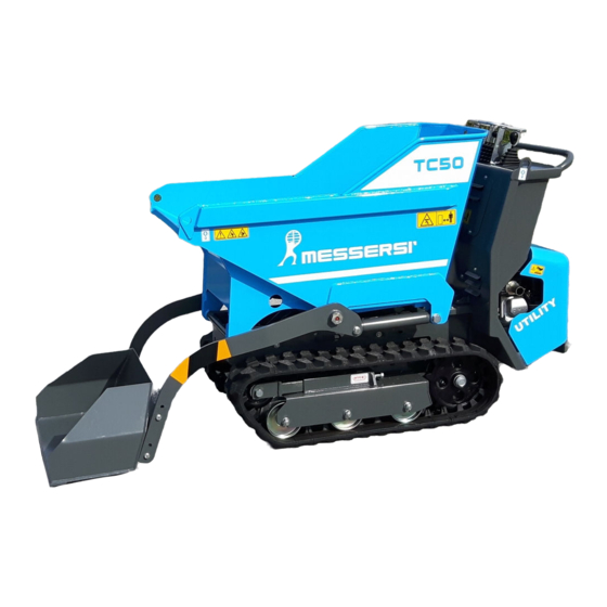
2.2 MAIN PARTS OF THE MACHINE 1 - CONTROL PANEL 2 - ENGINE 3 - MOBILE FOOTBOARD (OPTIONAL) 4 - ENGINE HOOD (OPTIONAL) 5 - SCREW TRACK TIGHTENER 6 - DUMP BODY OR LOAD BUCKET 7 - HATCH TO OPEN-CLOSE DUMP BODY OR BUCKET 8 - MACHINE LIFT HOOKS 9 - TRACK... -
Page 7: Characteristics - Technical Data
The machine has been designed and built for transporting and dumping of soil, sand, excavation debris and other loose materials suitable in terms of the characteristics and performance indicated in this manual. TC50 TC50/AV This machine has a manual hydraulic transmission; each lever independently controls the movement of each track, thus guaranteeing maximum control in all operating situations. - Page 8 TECHNICAL DATA TC50 TC50/AV Operating weight (without operator) Operating load Loading capacity: - piled full (SAE standard) 0.310 0.205 - level: sand/liquids 0.270 0.175 Engine tipo HONDA GX160 Max RPM 3600 Max. power at 3600 rpm HP/Kw 5.5/4.0 Displacement cm³...
- Page 9 Implementation of EEC Directive 14/2000 regarding limiting noise produced by operating machinery. = 101 dB Guaranteed noise level: = 80 dB Acoustic pressure at operator's ear: Implementation of EEC Directive 44/2002 regarding minimum safety and health prescriptions for on-the-job exposure to the risks derived from mechanical vibrations. Daily action values ...
-
Page 10: Safety - Operating Standards
3. SAFETY - OPERATING STANDARDS 3.1 SAFETY LABELS AND STICKERS Besides indicating the various operations to control and use the machine, the labels also highlight the risks related to operating the machine. Operators who normally wear eyeglasses must wear them to read the labels. Keep the labels clean and legible paying particular attention to the safety indications. -
Page 11: General Standards For Safety And Use
3.2 GENERAL STANDARDS FOR SAFETY AND USE The present manual contains the information required to run the machine. Contact the Manufacturer for any spare parts, accessories or information you might require. The tracked minitransporter fit with bucket or open dump body serves to carry and dump materials. - Page 12 GOING UP OR DOWN, WITH LOAD 30% MAX 30% MAX GOING UP OR DOWN, EMPTY 30% MAX 30% MAX TRAVELING OVER A FLAT SURFACE, EMPTY GOING UP OR DOWN, EMPTY AND WITH LOAD MAX 18 %...
- Page 13 USE OF THE OPERATOR FOOTBOARD: The FOOTBOARD must be LIFTED (max height) while the OPERATOR is on the GROUND. The FOOTBOARD must be LOWERED with the OPERATOR ON IT. Never walk behind the unit while the footboard is lowered. Whether the machine is running or off, to park the machine with full load on a slope of more than 10%, insert a safety wedge at the tracks.
- Page 14 Prevent foreign bodies (gravel, stones, debris, etc.) from wedging between the rubber tracks as this would create interference between the various transmission bodies and could damage or break them. HAZARDOUS ZONES ! Because of its operating characteristics, the machine has some pinch points (lowering the dump body onto the frame, bucket, tracks) and shearing points (dump body hatch).
-
Page 15: Lifting And Transporting
3.3 LIFTING AND TRANSPORTING See section 2.3 of this manual for the “overall dimensions of the machine”, while for the loading on a lorry by using ramps, follow what explained below. Close the loading/unloading areas, forbidding the entrance to foreign people and clearing the zone from obstacles and dangerous stuffs. - Page 16 ATTENTION!!! It is recommended to close the fuel valve every time the vehicle is transported or handled in order to prevent causing harm or damage. To load and unload the transporter from the truck, it is suggested to act as shown below. Particular attention has to be taken during the overcome of the connection between the ramps and the lorry loading platform, which can cause an excessive gradient.
-
Page 17: Hoisting And Transport
3.4 HOISTING AND TRANSPORT Kg 360 / 470 The machine must be lifted only when empty and carefully following the indications below: - There are four lift connections, two on the front of the bucket and two on the sides of the driver's station. (see figure). -
Page 18: Driving - Control Position
- ACCELERATOR LEVER - SPEED SELECTOR LEVER - LOAD BUCKET UP-DOWN LEVER – DRIVING LEVER FOR THE LIFTING OF THE UNLOADING SKIP (AVAILABLE ONLY ON TC50/AV) - LEFT TRACK LEVER - RIGHT TRACK LEVER - DRIVING HANDLEBAR To operate the various commands, follow the indications reported below:... -
Page 19: Driving
4.2 DRIVING “5” “6” To drive the machine, operate levers We will now take a close look at the operations required to drive forward, back and to steer. “5” “6” FORWARD: push levers forward simultaneously by the same amount. “5” “6”... - Page 20 TURNING LEFT WHEN DRIVING FORWARD: WITH THE MACHINE AT A STANDSTILL : - push lever “6” forward of lever “5” - (this maneuver is facilitated in SLOW drive) WITH THE MACHINE MOVING: pull lever “5” back vs. lever “6” TURNING LEFT WHEN BACKING UP: WITH THE MACHINE AT A STANDSTILL: - pull lever “6”...
-
Page 21: Services
“2” Lever : speed selector LEVER FORWARD: FAST SPEED LEVER BACK: SLOW SPEED 4.3 SERVICES “3” Lever : bucket or dump body control This lever controls tipping of the dump body To lift the dump body, push the lever forward; to lower the body, just pull the lever back. - Page 22 “4” Lever : driving lever for the lifting of the unloading skip Activation of the lever allows to lift the frame-loading bucket unit for high unloading . Pull the lever down to lift the frame. Push up the lever to lower the bucket. “1”...
-
Page 23: Starting Up And Stopping The Engine
4.4 STARTING UP AND STOPPING THE ENGINE The minitransporter is powered by an endothermic engine. By way of example, a synthesis of the engine user's manual is reported below. For further details, see the user's manual for the engine installed in the machine. The engine is started up with a self-winding starter. - Page 24 HOW TO ENSURE EXCELLENT START-UP EVERY TIME MANUAL START-UP OPERATION No. 1 – lower the footboard and press the fuel lever (located on the left side of the engine) all the way to the right. OPERATION No. 2 - set the "STARTER" air lever to the intermediate position if the engine is warm and to the far left if it is cold.
-
Page 25: General Maintenance
5. GENERAL MAINTENANCE 5.1 GREASE POINTS 50 h 50 h 50 h 50 h 50 h Refill the grease points at the times indicated. (for the type of grease, follow the indications in the lubricant table) Always keep the lubricators clean and efficient, and replace them when they are worn or damaged. -
Page 26: Checks And Controls
5.2 CHECKS AND CONTROLS Pay particular attention to the items indicated below: 1 – HYDRAULIC OIL TANK FILLING CAP 2 – FUEL CAP 3 – AUTOMATIC DUMPER HATCH OPENING DEVICE 4 – TRACK TENSION REGULATION DEVICE 5 – DISCHARGE HYDRAULIC OIL FILTER 1 –... -
Page 27: Tightening The Tracks
2 – FUEL CAP Never fill the tank until gasoline overflows. Always leave a space (approximately 1/5) for the fuel to expand inside of the tank. WARNING! : ENGINE REQUIRES LEAD-FREE GASOLINE TANK CAPACITY 3.6 liters RANGE approximately 4.0 hours 3 –... - Page 28 If the distance is greater, proceed as follows: – loosen lock-nut “A” (with a 27 wrench). – tighten screw “B” (with a 27 wrench) until the correct tightness is restored – lock screw “B” tightening lock-nut “A” thoroughly. At this point, track tightness has been restored to the original tension found with new tracks.
- Page 29 OPERATING ANOMALIES AND PROBLEMS FAILURE OF THE TRACK STEEL CORDS - Excessive tightening of the track plus use on gravel and loose material that can accumulate between the track and the carriage. - Track jumping the guide wheels. - Strong friction in cases of excessively frequent and rapid changes of direction. WEAR OR BREAKAGE OF THE METAL CORES - Excessive tightening of the tracks.
-
Page 30: Replacing The Discharge Hydraulic Oil Filter
5.4 REPLACING THE DISCHARGE HYDRAULIC OIL FILTER The filter is set on the outside, under the engine hood (see figure). Replace the filter after the first 50 HOURS of operation and every 500 HOURS thereafter. Unscrew the filter “F” and replace it with another having the same characteristics: Filter rating: 10 micron. -
Page 31: Explosion Engine
5.6 EXPLOSION ENGINE For operation, refueling, start-up and shutdown, controls and cleaning, and for maintenance, follow the indications given in the User’s Manual that the Manufacturer has supplied with the machine. REFUEL ENGINE WITH LEAD-FREE GASOLINE 5.7 MAINTENANCE SUMMARY TABLE HOURS FOR FIRST OPERATION REPLACEMENT... -
Page 32: Hydraulic Transmission System And Services
6. HYDRAULIC TRANSMISSION SYSTEM AND SERVICES 1 - HYDRAULIC GEAR PUMP FOR SERVICES AND 2nd SPEED 2 - HYDRAULIC GEAR PUMP CONNECTED TO HYDRAULIC MOTOR CONTROLLING LEFT TRACK 3 - HYDRAULIC GEAR PUMP CONNECTED TO HYDRAULIC MOTOR CONTROLLING RIGHT TRACK 4 - ENDOTHERMIC ENGINE REFERENCE VALUES FOR CALIBRATION OF THE HYDRAULIC SYSTEM AND SERVICES SYSTEM. - Page 33 Start the checks following the indications given below. The reading must match that indicated in the previous table. Disconnect the hydraulic hoses only at point (P1) and insert the 3-way connection for control and calibration of the service system, and use points (P2 and P3) to control and calibrate the translation system.
- Page 34 WARNING ! Carefully follow the indications supplied, remembering that the checks and pressure controls must be performed with the hydraulic oil at operating temperature (approximately 50-60°C). WHEN CONNECTING AND DISCONNECTING THE POINTS FOR INSERTING THE MANOMETER, CHECK FOR OIL LEAKS. IT IS ADVISABLE TO PERFORM THE ABOVE OPERATION OVER AN IMPERMEABLE OR PLASTIC SHEET.
-
Page 35: Troubleshooting: Causes And Remedies
7. TROUBLESHOOTING: CAUSES AND REMEDIES PROBLEM CAUSE SOLUTION There is no oil in the tank Check the level and top up if necessary Air in the hydraulic Check that the piping and transmission system connections are intact The machine moves jerkily Hydrost. - Page 36 Check and replace if Hydraulic piping failure necessary Distributor pressure too low Check and restore if The dump body does necessary not rise Check and replace if Cylinder or gasket damaged necessary Hydraulic pipe broken Check and replace if between hydraulic motor and The machine does not move necessary pump...
-
Page 37: Notes On Maintenance
8. NOTES ON MAINTENANCE HOURS PARTS DATE WORK PERFORMED WORK INVOLVED...
Need help?
Do you have a question about the TC50 and is the answer not in the manual?
Questions and answers