
Related Manuals for mundoclima KJR-120G2/TFBG-E-02


Summary of Contents for mundoclima KJR-120G2/TFBG-E-02
- Page 1 KJR-120G2/TFBG-E-02 Manual de instalación y usuario Installation and owner's manual CL09210 www.mundoclima.com www.mundoclima.com ES-EN...
- Page 2 ....................................................
- Page 3 Manual de usuario e instalación ● Este manual ofrece una descripción detallada de las precauciones que se han de tener en cuenta durante el funcionamiento del equipo. ● Para asegurar el buen desempeño del control remoto cableado lea cuidadosamente este manual antes de encender la unidad.
-
Page 4: Table Of Contents
ÍNDICE 1. MEDIDAS DE SEGURIDAD ................2. ACCESORIOS DE INSTALACIÓN ..............3. PROCEDIMIENTO DE INSTALACIÓN ............. 4. APÉNDICE INSTALAR EL CONTROL CABLEADO CON 1 SMART KIT (WIFI) .. 14 5. ESPECIFICACIONES..................15 6. CARACTERÍSTICAS Y FUNCIONES DEL CONTROL CABLEADO..... 7. -
Page 5: Medidas De Seguridad
1. MEDIDAS DE SEGURIDAD Lea cuidadosamente las precauciones de seguridad antes de instalar el dispositivo. Se deben cumplir las indicaciones de seguridad que se describen a continuación. Significa mala manipulación y puede provocar la muerte o lesiones graves. ADVERTENCIA Significa mala manipulación y puede provocar lesiones o pérdidas materiales. -
Page 6: Accesorios De Instalación
2. ACCESORIOS DE INSTALACIÓN Selección de la ubicación No instale el control en un sitio cubierto de aceite pesado, ni donde haya vapores o gases sulfurosos, de lo contrario este producto se podrá deformar y averiarse. Preparación previa a la instalación 1. - Page 7 2. ACCESORIOS DE INSTALACIÓN PRECAUCIÓN DE INSTALACIÓN DEL CONTROL CABLEADO 1. Este manual proporciona el método de instalación del control cableado. Consulte el diagrama eléctrico de este manual de instalación para conectar el control remoto cableado a la unidad interior. 2.
-
Page 8: Procedimiento De Instalación
MÉTODO DE INSTALACIÓN Dimensiones del control remoto cableado 120mm 18.5mm 46mm 83.5mm 123mm Fig. 3-1 62mm Diagrama de conexión del cableado Fig. 3-2 Conector CN40 ------------------------------------------- Rojo Rojo (CN38 en modelos ------------------------------------------- MUCSR-24 a 60-H11-I) Negro Negro ------------------------------------------- Amarillo Amarillo ------------------------------------------- Marrón Marrón... - Page 9 MÉTODO DE INSTALACIÓN Conexión Placa principal Cable de conexión principal (6m, si necesita más Cable del control puede comprar otro cable (CL97448) de 6m CL97448) CN40 ó CN38 en modelos MUCSR- 24 a 60 H11-I Fig. 3-3 Enchufe el conector hembra del cable conectado al puerto CN40 de la placa principal con el conector macho del cable de conexión (CL97448).
- Page 10 MÉTODO DE INSTALACIÓN Retirar la parte superior del control cableado Introduzca un destornillador plano en las ranuras de la parte inferior del control (2 lugares). Retire la parte superior del control cableado (Fig.3-4) NOTA: La placa de circuito impreso está montada en la parte superior del control Ranuras cableado.
- Page 11 MÉTODO DE INSTALACIÓN Para el montaje del control sobre una caja universal, fije la placa trasera a la caja universal con 2 tornillos (M4 x 25) y fíjela en la pared con 1 tornillo (M4 x 20). (Fig.3-6) Placa trasera Caja eléctrica universal Tornillos (M4 ×...
- Page 12 MÉTODO DE INSTALACIÓN 7. Cableado a la unidad interior Hay tres métodos: 1 Desde la parte trasera; 2 Desde el fondo; 3 Desde arriba; 4. Haga, con una tenaza, una muesca en la pieza para que pase el cableado.
- Page 13 MÉTODO DE INSTALACIÓN NOTA: NO permita que entre agua en el control cableado. Utilice una trampa y la masilla para sellar los cables. Masilla Trampa Masilla Masilla Trampa Trampa Fig. 3-8 8. Vuelva a colocar la parte superior del control cableado Después de ajustar y fijar la tapa superior, evitar sujetar con una abrazadera el cableado durante la instalación.
-
Page 14: Apéndice Instalar El Control Cableado Con 1 Smart Kit (Wifi)
4. APÉNDICE INSTALAR EL CONTROL CABLEADO CON UN SMART KIT (MÓDULO WIFI) Instalación del control cableado KJR-120G2 con el Smart Kit (Módulos WIFI: CL97480; CL97806; CL09002) Conecte el Smart Kit (WIFI) a la placa principal de la unidad interior (puerto CN40) y conecte el control cableado KJR-120G2 al Smart Kit (puerto CN3) según el siguiente diagrama: CN40 PLACA PRINCIPAL DE LA UNIDAD... -
Page 15: Especificaciones
5. ESPECIFICACIONES DC 12V Voltaje de entrada 23~110 ºF (-5~43 ºC) Temperatura ambiente exterior 40 % ~ 90 % humedad relativa Humedad relativa Especificaciones del cableado Tipo de cable Longitud total del Tamaño cable ≤ 20 m 0.74mm Cable apantallado (1.25mm ) ≤... -
Page 16: Características Y Funciones Del Control Cableado
Muestra la temperatura interior Temporizador semanal Funciones: Selección de Modo: Auto - Cool (Refrig.) - MODELO: KJR-120G2/TFBG-E-02 Dry (Secado) -Heat (Calef.) -Fan (Vent.) Velocidad del ventilador: Auto-Low (Baja) - Med (Media) - High (Alta) Oscilación (en algunos modelos) Temporizador ON/OFF... -
Page 17: Pantalla Del Control Cableado
7. PANTALLA DEL CONTROL CABLEADO 1. Indicación del modo de Func. 8. Indicador de la función Turbo/Calor Auxiliar 2. Indicación de la vel. del ventilador 9. Indicador °C / °F 3. Indicador de oscilación izqu.-dcha. 10. Lectura de temperatura 4. Indicador oscilación arriba-abajo 11. -
Page 18: Botones Del Control Cableado
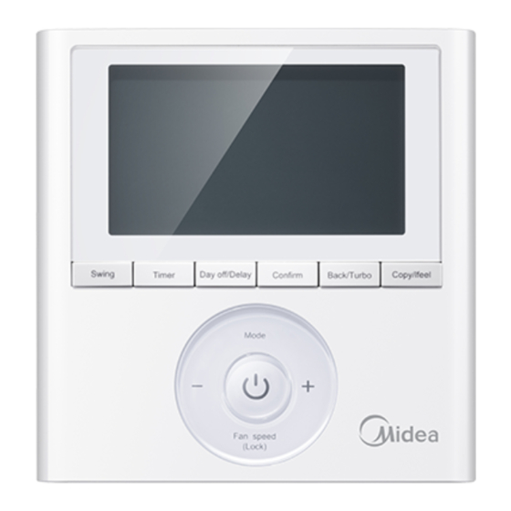
8. BOTONES DEL CONTROL CABLEADO Copy/ Swing Timer Day off/Del Confirm Back/Turbo Follow me Mode Fan speed (Lock) 1. Mode (Modo) 6.Temporizador 2. Power (ON/OFF) 7. Day off/Del (Día libre/Borrado) 8. Copy/Follow me (Copiar / «Follow me») 3. Adjust (Ajuste) 4. -
Page 19: Ajustes Previos
9. AJUSTES PREVIOS Ajusta la fecha y hora actual Pulse TIMER durante 3s o más. La pantalla del temporizador Timer parpadea. Pulse + o - para ajustar la fecha. La fecha seleccionada parpadea. parpadea. El ajuste de la fecha está completo y el ajuste de la hora Timer está... -
Page 20: Funcionamiento
10. FUNCIONAMIENTO Encender/apagar Pulse el botón «Power» (ON/OFF) Ajustes del modo de funcionamiento Pulse MODE para ajustar el modo de funcionamiento. Mode (Mod Ajuste de temperatura ambiente Pulse + ” o− para ajustar la temperatura unidad interior: (17~30 ó 31 ℃) según modelos. ambiente. - Page 21 10. FUNCIONAMIENTO Ajuste de la velocidad del ventilador Pulse FAN SPEED para ajustar la velocidad del ventilador NOTA: Esta función no está disponible en los modos AUTO o SECADO. Fan speed (Lock) Selección del lugar de lectura de la temperatura ambiente Pulse FOLLOW ME para seleccionar si la temperatura ambiente se detecta en la unidad interior o en el control cableado.
- Page 22 10. FUNCIONAMIENTO Bloqueo para niños Pulse LOCK durante 3 segundos para de esta forma activar el bloqueo para niños y así todos los botones del control remoto cableado quedarán bloqueados. Pulse de nuevo durante 3 segundos para desactivar. Fan speed (Lock) NOTA: Cuando la función de bloqueo para niños está...
- Page 23 10. FUNCIONAMIENTO Función turbo/calor auxiliar (en algunos modelos) • Pulse TURBO para activar/desactivar la función • Turbo/Calor Auxiliar. La función turbo hace que el Back/Turbo aparato alcance la temperatura deseada en el menor tiempo posible. • Cuando el usuario pulsa TURBO en el modo COOL, la unidad se ajusta a la máxima velocidad del ventilador para poner en marcha el proceso de refrigeración.
- Page 24 10. FUNCIONAMIENTO Función de oscilación (Solo para la unidad con función de oscilación automática izquierda y derecha) 1 Oscilación arriba-abajo Swing (Oscila Pulse el botón Swing para iniciar la función de oscilación arriba-abajo Púlsalo de nuevo para parar. Cuando se activa la función oscilación arriba-abajo, aparecerá el símbolo 2 Oscilación izquierda-derecha Swing (Oscila...
- Page 25 10. FUNCIONAMIENTO Función de oscilación (Para los modelos sin función de oscilación automática izquierda y derecha) Dirección de flujo de aire y oscilación arriba-abajo ● Utilice SWING para ajustar la dirección del flujo de aire hacia arriba y hacia abajo. 1.
-
Page 26: Funciones Del Temporizador
11. FUNCIONES DEL TEMPORIZADOR TEMPORIZADOR Temporizador semanal Use para ajustar los tiempos de funcionamiento para cada día de la semana. Temporizador de encendiido Se utiliza para poner en funcionamiento del aire acondicionado. El temporizador funciona y el aire acondicionado se pone en marcha después de que pase el período de tiempo programado. - Page 27 11. FUNCIONES DEL TEMPORIZADOR TEMPORIZADOR Ajuste del temporizador de encendido o apagado Pulse TIMER para seleccionar la opción Timer No display display Confirm Pulse CONFIRM y el icono del reloj parpadeará (Confir P.ej. ajuste del tiempo a las PM 6:00 Pulse + o −...
- Page 28 11. FUNCIONES DEL TEMPORIZADOR TEMPORIZADOR Ajuste del temporizador de encendido y apagado Pulse Timer para seleccionar Timer Pulse CONFIRM y el icono del reloj parpadeará Confirm Confirm Pulse + o - para ajustar el temporizador de encendido y luego pulse Confirm. Pulse + o - para ajustar el temporizador de apagado.
-
Page 29: Temporizador Semanal
TEMPORIZADOR SEMANAL TEMPORIZADOR Ajuste del temporizador semanal Pulse Timer para seleccionar el y pulse Confirm. Timer Confirm Ajuste de los días de la semana Pulse + o - para seleccionar el día de la Confirm semana y luego pulse CONFIRM. Ajuste el temporizador de activación del ajuste del temporizador 1 Pulse+ o la tecla−... - Page 30 12. TEMPORIZADOR SEMANAL TEMPORIZADOR IMPORTANTE: Se pueden programar hasta 8 eventos en un día. Se puede programar MODO, TEMPERATURA y velocidades del VENT. en cada evento p.ej. Martes escala de tiempo 1 Ajuste del temporizador Pulse + y - para ajustar la hora y luego pulse Confirm CONFIRM Ajuste del modo de funcionamiento...
- Page 31 12. TEMPORIZADOR SEMANAL TEMPORIZADOR Ajuste de la velocidad del ventilador Pulse + y - para ajustar la velocidad del Confirm ventilador y luego pulse CONFIRM. NOTA: Este ajuste no está disponible en los modos AUTO, SECADO u OFF. Se puede ajustar varias veces el temporizador repitiendo los pasos del 3 al 7.
- Page 32 12. TEMPORIZADOR SEMANAL TEMPORIZADOR Funcionamiento del temporizador semanal Presione Timer para seleccionar el , y luego el temporizador se inicia automáticamente. Para encender Timer p.ej. Para cancelar Pulse «Power» para cancelar el modo temporizador. El temporizador también se puede cancelar cambiando Timer el modo del temporizador mediante TIMER.
- Page 33 12. TEMPORIZADOR SEMANAL TEMPORIZADOR Pulse DAY OFF (día libre) para crear un día libre. El símbolo permanece oculto. P.ej. El DAY OFF se fija para el miércoles Ajuste el DÍA LIBRE para los otros días repitiendo los pasos 2 y 3. Pulse BACK para volver al temporizador semanal.
- Page 34 12. TEMPORIZADOR SEMANAL TEMPORIZADOR Copy/ Pulse COPY, las letras CY aparecen en la pantalla. Follow me Pulse + o − para seleccionar el día al que va a copiar. Pulse COPY para confirmar. Copy/ Follow me El símbolo parpadea rápidamente. ej.
- Page 35 12. TEMPORIZADOR SEMANAL TEMPORIZADOR Borrar la escala de tiempo de un día. Confirm Durante el ajuste del temporizador semanal pulse CONFIRM pulse CONFIRM. Pulse + y - para seleccionar el día de la Confirm semana y luego pulse CONFIRM. Day off/Del Pulse + y - para seleccionar la hora de ajuste que desea borrar.
-
Page 36: Ajustar La Presión Estática
13. AJUSTAR LA PRESIÓN ESTÁTICA Utilizar el control cableado para ajustar autom. la presión estática (uds. conducto) • Puede utilizar la función de ajuste automático del flujo de aire de la unidad para ajustar la presión estática. • El ajuste automático del caudal de aire es el volumen de aire de soplado que se ha ajustado automáticamente a la cantidad nominal. -
Page 37: Códigos De Error
14. CÓDIGOS DE ERROR Si el sistema no funciona correctamente excepto los casos antes mencionados, es evidente que hay averías, analice el sistema según los siguientes procedimientos. Nº Código Descripción Error de comunicación entre el control cableado y la unidad interior La función de elevación del panel es anormal La rejilla de entrada de aire no encaja bien en el cassette Error en la secuencia de fases de la fuente de alimentación... - Page 38 Installation and Owner's Manual ● This manual gives detailed description of the precautions that should be brought to your attention during operation. ● In order to ensure correct service of the wired controller please read this manual carefully before using the unit. ●...
- Page 39 CONTENTS 1. SAFETY PRECAUTION....................40 2. INSTALLATION ACCESSORY..................41 3. INSTALLATION METHOD....................43 4. APPENDIX INSTALL THE WIRE CONTROLLER WITH A SMART KIT (WIFI)... 5. SPECIFICATION......................6. WIRED CONTROLLER FEATURES AND FUNCTIONS........... 7. WIRED CONTROLLER DISPLAY.................. 8. WIRED CONTROLLER BUTTONS................9. PREPARATORY OPERATION..................10.
-
Page 40: Safety Precaution
1. SAFETY PRECAUTION Read the safety precautions carefully before installing the unit. Stated below are important safety issues that must be obeyed. Means improper handling may lead to personal death or severe injury. WARNING Means improper handling may lead to personal injury or property loss. CAUTION WARNING Please entrust the distributor or professionals to install the unit. -
Page 41: Installation Accessory
2. INSTALLATION ACCESSORY Select the installation location Don’t install at the place where cover with heavy oil, vapor or sulfureted gas, otherwise, this product would be deformed that would lead to system malfunction. Preparation before installation 1. Please confirm that all the following parts you have been supply. Name Qty. - Page 42 2. INSTALLATION ACCESSORY WIRED CONTROLLER INSTALLATION PRECAUTION 1. This manual provides the wired controller installation method. Refer to the wiring diagram in this installation manual to wire the wired controller with the indoor unit. 2. The wired controller works in a low voltage loop circuit. Do not connect directly to 208/230V and 460V.
-
Page 43: Installation Method
3. INSTALLATION METHOD 1.Wired Remote Controller Dimensions 120mm 18.5mm 46mm (4.7”) (0.7”) (1.8”) 83.5mm 123mm (3.3”) (4.8”) 62mm (2.4”) Fig 3-1 2.Wiring Connection Diagram Insert of the mainboard CN40 ----------------------------------- ----------------------------------- black black yellow ----------------------------------- yellow ----------------------------------- brown brown 4-Core Shield Cable, the length Wire controller Indoor unit main board is decided by installation... - Page 44 3. INSTALLATION METHOD 3.Wiring figure Main board The connection cable (6m, if need more you can 4-core shielding wire buy other 6m wire CL97448) CN40 Fig 3-3 Connect the female joint of the wires group from the mainboard with the male joint of the connective wires group. (See Fig.3-3) Connect the other side of the connective wires group with the male joint of the wires group leads from the wire controller.(See Fig.3-3) Install the Adapter Board and the Display Board on the High Wall...
- Page 45 3. INSTALLATION METHOD 4.Wire controller upper part Remove Insert a flat screwdriver into the slots in the lower part of the wire controller (2 places). Remove the upper part of the wire controller (Fig.3-4) NOTE: The PCB is mounted in the upper part Slots of the wired controller.
- Page 46 3. INSTALLATION METHOD For switch box mounting, fasten the back plate on the switch box with 2 screws (M4x25) and fasten it on the wall with 1 screw (M4x20). (Fig.3-6) Back plate Switch box Screw (M4×20) Screws (M4×25) Fig 3-6 NOTE: Place on a flat surface.
- Page 47 3. INSTALLATION METHOD 7. Wire the indoor unit There are three methods: 1 from the rear; 2 from the bottom; 3 from the top; 4. Notch the part for the wiring to pass through with a nipper tool.
- Page 48 3. INSTALLATION METHOD NOTE: DO NOT allow water to enter the remote control. Use the trap and putty to seal the wires. Putty Trap Putty Putty Trap Trap Fig 3-8 8. Reattach the wire controller’s upper part While adjusting and mounting the upper case, avoid clamping the wiring during installation.
-
Page 49: Appendix Install The Wire Controller With A Smart Kit (Wifi)
4. APPENDIX INSTALL THE WIRE CONTROLLER WITH A SMART KIT (WIFI) Installation of the wired controller KJ R -120G2 with the Smart Kit (WIFI modules: CL97480; CL97806; CL09002) Note: On the MUCR-H9 series, disconnect the aerial connector of wire that is connected to the CN40 port in the Indoor unit main board (marked with an arrow in the following diagram: Disconnect CN40... -
Page 50: Specification
5. SPECIFICATION DC 12V Input voltage Ambient temperature 23~110℉(-5~43℃) RH40%~RH90% Ambient humidity Wiring specifications Wiring type Total length Size <20m 0.74mm Shielded vinyl cord or cable (1.25mm ) <50m... -
Page 51: Wired Controller Features And Functions
Timer Day off/Del Confirm Back/Turbo Follow me ℃ ℉ Weekly Timer Mode Fan speed (Lock) MODEL: KJR-120G2/TFBG-E-02 Function: Mode: choose Auto-Cool-Dry-Heat-Fan Fan speed: Auto-Low-Med-High Swing(on some models) Timer ON/OFF Temp setting Weekly Timer Follow me Child Lock Clock Panel function (on some models) -
Page 52: Wired Controller Display
7. WIRED CONTROLLER DISPLAY 1. Operation mode indicator 8. Turbo/Auxiliary Heat function indicator 2. Fan speed indicator 9. °C / °F indicator 3. Left-right swing indicator 10. Temperature display 4. Up-down swing indicator 11. Lock indicator 5. Panel function indicator 12. -
Page 53: Wired Controller Buttons
8. WIRED CONTROLLER BUTTONS Copy/ Swing Timer Day off/Del Confirm Back/Turbo Follow me Mode Fan speed (Lock) 1. Mode 6. Timer 2. Power 7. Day Off/Del 3. Adjust 8. Copy/Follow me 4. Fan Speed 9. Back/Turbo 5. Swing 10. Confirm... -
Page 54: Preparatory Operation
9. PREPARATORY OPERATION Set the current day and time Press TIMER for 3s or more. The timer displays flashes. Timer Press + or − to set the date. The selected date flashes. Date setting is complete and the time setting is ready after Timer pressing TIMER or if nothing is pressed in 10 seconds. -
Page 55: Operation
10. OPERATION To start/stop operation Press the Power button. To set the operation mode Operation mode setting Press MODE to set the operation mode. Mode (Heat function is invalid for cool only type unit) Room temperature setting Press + or − to set the room temperature. Indoor Setting Temperature Range: 62~86℉(17~30℃)/62~88℉(17~31℃(depending on models)). - Page 56 10. OPERATION Fan speed setting Press FAN SPEED to set the fan speed NOTE: This function is unavailable in the AUTO or DRY modes. Fan speed (Lock) Room temperature sensor selection Press FOLLOW ME to select whether the room temperature is detected at the indoor unit or at the wired controller.
- Page 57 10. OPERATION Child lock function Press LOCK for 3 seconds to activate the CHILD LOCK feature and lock all buttons on the wired controller. Press again for 3 seconds Fan speed to deactivate. (Lock) NOTE: When the child lock function is activated, lock image appears.
- Page 58 10. OPERATION Turbo/Auxiliary Heat function (on some models) • Press TURBO to activate/deactivate the Turbo/Auxiliary Back/Turbo Heat function. The turbo function sets the unit to reach the user’s present temperature in the shortest amount of time possible. • When the user presses TURBO in the COOL mode, the unit sets to the highest fan speed setting to jump−start the cooling process.
- Page 59 10. OPERATION Swing function (For the unit with left & right auto swing function only) 1 Up-Down swing Swing Press the Swing button to start up-down swing function. Press it again to stop. When the Up-Down swing function is activated,the mark appears.
- Page 60 10. OPERATION Swing function (For the unit without left & right auto swing function models) Up-Down airflow direction and swing Swing Use SWING to adjust the up and down airflow direction. 1.Every time the user presses SWING, the louver swings six degrees. 2.Press and hold SWING for 2 seconds, it changes to the UP−DOWN SWING mode.
-
Page 61: Timer Functions
11. TIMER FUNCTIONS WEEKLY timer Use to set the operating times for each day of the week. On timer Use to start the air conditioner operation. The timer operates and the air conditioner operation starts after the time has passed. Off timer Use to stop the air conditioner operation. - Page 62 11. TIMER FUNCTIONS To set the On or Off TIMER Press Timer to select the Timer No display Press Confirm and the Clock display flashes Confirm ex.Off timer set at PM 6:00 Press + or − to set the time. After the time is set, the timer starts or stops automatically.
- Page 63 11. TIMER FUNCTIONS To set the On and Off TIMER Press Timer to select the Timer Confirm Press Confirm and the Clock display flashes. Confirm Press the button + or - to set the On timer and then press Confirm. Press + or - to set the Off timer.
-
Page 64: Weekly Timer
12. WEEKLY TIMER Weekly timer setting Press Timer to select the and press Confirm. Confirm Timer Day of the week setting Press + or − to select the day of the week Confirm and then press CONFIRM. ON timer setting of timer setting 1 Press + and −... - Page 65 12. WEEKLY TIMER IMPORTANT: Up to 8 scheduled events can be set on one day. Various events can be scheduled in either MODE, TEMPERATURE and FAN speeds. ex.Tuesday time scale 1 Time setting Press + and − to set the time then press Confirm CONFIRM.
- Page 66 12. WEEKLY TIMER Fan speed setting Press + and − to set the fan speed then press Confirm CONFIRM. NOTE: This setting is unavailable in the AUTO, DRY or OFF modes. Different scheduled events can be set by repeating steps 3 through 7. Additional days, in a one week period, can be set by repeating steps 3 through 8.
- Page 67 12. WEEKLY TIMER WEEKLY timer operation To start Press Timer to select the , and then the timer Timer starts automatically. To cancel Press Power to cancel the timer mode. The timer mode can also be canceled by changing the Timer timer mode using Timer.
- Page 68 12. WEEKLY TIMER Press DAY OFF to create an off day. Day off/Del mark is hidden ex.The DAY OFF is set for Wednesday Set the DAY OFF for other days by repeating the steps 2 and 3. Back/Turbo Press BACK to revert to the weekly timer. ●...
- Page 69 12. WEEKLY TIMER Press COPY, the letters CY appear on the LCD. Copy/ Follow me Press + or − to select the day to copy to. Press COPY to confirm. Copy/ Follow me mark flashes quickly ex. Copy the setting of Monday to Wednesday Other days can be copied by repeating steps 4 and 5.
- Page 70 12. WEEKLY TIMER Delete the time scale in one day. During the weekly timer setting, Confirm press CONFIRM. Press + and − to select the day of the week Confirm and then press CONFIRM. Day off/Del Press + and − to select the setting time want to delete. The setting time, mode, temperature and fan speed appear on the LCD.
-
Page 71: Set External Static Pressure
13. SET EXTERNAL STATIC PRESSURE Using the wire controller to set external static pressure (duct units). • You can use the unit’s automatic airflow adjustment function to set external static pressure. • Automatic airflow adjustment is the volume of blow-off air that has been automatically adjusted to the quantity rated. -
Page 72: Fault Alarm Handing
14. FAULT ALARM HANDING If the system does not properly operate except in the aforementioned cases or the aforementioned malfunctions are evident, investigate the system according to the following procedures. Nº Code Description Error of communication between wire controller and indoor unit The lifting filter function is abnormal The air inlet grill doesn't fit well of Super slim four-way cassette Error of power supply phase sequence Error of communication between indoor unit and outdoor unit T1 temp. sensor is abnormal T2A temp. sensor is abnormal T2B temp. sensor is abnormal T3/T4 temp. sensor is abnormal or compressor discharge temp. sensor is abnormal ... - Page 73 C/ NÁPOLES 249 P1 08013 BARCELONA ESPAÑA / SPAIN (+34) 93 446 27 80 QSX001IU-120G2 www.mundoclima.com 16117100A13350 20190130...
Need help?
Do you have a question about the KJR-120G2/TFBG-E-02 and is the answer not in the manual?
Questions and answers