
Related Manuals for Sfere LNF96ZY


Summary of Contents for Sfere LNF96ZY
- Page 1 Multi-function Power Meter User Manual This Manual is applicable to the products with following models: LNF96ZY...
- Page 2 Thank you for selecting multi-function power meter of Jiangsu Sfere Electric Co., Ltd. To make you use this device safely, correctly and efficiently, please read this manual carefully and pay attention to the following points during the using. CAUTION: The device must be installed and overhauled by professional personnel;...
-
Page 3: Table Of Contents
Contents I. Brief Introduction to Product ................1 1.1 Quoted Standards ...................1 1.2 Product Overview ....................1 II. Technical Parameters ..................2 III. Installation and Wiring..................3 3.1 Instrument Dimensions ...................3 3.2 Installation Mode ....................4 3.3 Functions Description of Wiring Terminal ............5 3.4 Connection of Input Signal Line ..............6 IV. - Page 4 System Setting Data ....................42 System Setting Data ....................63...
-
Page 5: Brief Introduction To Product
Environmental testing - Part 2-30 1.2 Product Overview The LNF96ZY multi-functional power instrument can be used to measure various frequently used power parameters and two-way electric energy, and has functions such as digital communication, switching value input, relay output, electric energy pulse output and analog output. -
Page 6: Technical Parameters
II. Technical Parameters Table 2-1 Technical Parameters Parameters U, I: Class 0.5; P, Q, PF: Class 0.5; active energy: 0.5S; reactive Accuracy energy: Class 2; analog output: Class 0.5 Display Mode Three-row LCD display Measurement network Three-phase four-wire, three-phase three-wire, single phase Rated value AC100V, AC380V Overload... -
Page 7: Installation And Wiring
III. Installation and Wiring 3.1 Instrument Dimensions Figure 3.1 Diagram of Instrument Dimensions Table 3-1 Table of Instrument Dimensions (mm) Minimum Installation Total Length Panel Installation Distance Hole Size Dimension Dimension s×y l×h a×b Horizontal Vertical 96×96 90×90 91×91... -
Page 8: Installation Mode
3.2 Installation Mode Figure 3-2 Front View Figure 3-3 Rear View Drill a hole of s×y (mm) on the fixed power distribution cabinet; Take out the instrument, loosen the screw, and take down the fixing support; The instrument is embedded into the installation hole from front face; Insert the fixing support of instrument, screw down the screw or push on the support to fix the instrument. -
Page 9: Functions Description Of Wiring Terminal
3.3 Functions Description of Wiring Terminal Functional wiring terminals of the instrument adopt uniform No., and its function is shown as below: Power supply AC/DC80-270V Current signal 4,5,6,7,8,9 Three-phase current input Voltage signal 11,12,13,14 Three-phase voltage input Relay output 15—18 2 circuits of relay output Analog output 30—31... -
Page 10: Connection Of Input Signal Line
3.4 Connection of Input Signal Line Three phase three wire, Three phase three wire, 2CT, no PT 2CT, 2PT 13 14 13 14 Three phase four wire, Three phase four wire, 3CT, no PT 3CT, 3PT 13 14 12 13 Description of Wiring: The input voltage shall not be higher than the rated input voltage (100V or 380V) of product;... -
Page 11: Menu Display And Programming
must be consistent with wiring mode set in the instrument; otherwise, the measurement data of instrument will be incorrect. IV. Menu Display and Programming 4.1 Panel Description and Using 1-Meter model: 2 - Display intaface to display related measurement and programming information;... -
Page 12: Menu Introduction And Operation
4.2 Menu Introduction and Operation The measurement display of meter includes electric quantity and electric energy, and pressing “ ” or “ ” key can display measurement data in a circulating way, Menu pressing “ ” key can realize rapid display switching between electric quantity and electric energy. - Page 13 Three-phase current. left figure represents that the three-phase current Ia= 5.011A, Ib=5.012A, Ic=5.013A. Three-phase active power. The left figure represents that the three-phase active power Pa=5701W, Pb=5702W, Pc=5703W. Three-phase reactive power. The left figure represents that the three-phase reactive power Qa = 680.5var, Qb = 680.6var, Qc = 680.7var.
- Page 14 Total active power. The left figure represents that the total active power P=5700W. Total reactive power. The left figure represents that the total reactive power Q=2200var. Total apparent power. left figure represents that the total apparent power S= 6700VA. Three-phase power factor. The left figure represents that the three-phase power factor PFa=0.932, PFb=0.931.
- Page 15 Total power factor. The left figure represents that the total power factor PF=0.980. Neutral current: calculated neutral current Digital input. 12 in the left figure respectively corresponds to 2 circuits of switching value input, and when there is signal input, the corresponding digit will flicker.
-
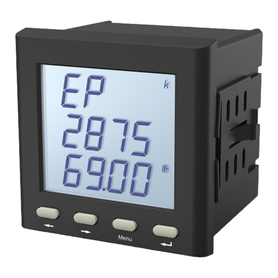
Page 16: Display Of Electric Energy
4.2.2 Display of Electric Energy The display interface of electric energy respectively displays positive/negative active electric energy, sensitive/capacitive reactive electric energy, and the description of display interface is shown as below: Table 4-2 Display Interface of Electric Energy Display Interface of Electric Description Energy Total active electric energy. -
Page 17: Thd Display
Total negative reactive electric energy. The left figure represents that the total negative = reactive electric energy 150020.05kvarh. 4.2.3 THD Display When "P.THD" is displayed in main menu, the harmonic wave display interface will enter. The harmonic wave display interface to display the total harmonic distortion of each phase voltage and current, respectively. - Page 18 Displays the total harmonic distortion (THD) of voltage; in the left figure, the total harmonic distortion of Uc = 4.03%. Press the Confirm key to display the sub-harmonic ratio. Displays the total harmonic distortion (THD) of current; in the left figure, the total harmonic distortion of Ia =3.01% Press the Confirm key to display the sub-harmonic ratio.
- Page 19 Display total harmonic distortion (HTD) of voltage for three-phase three-wire; in the left figure, the total harmonic distortion of Uab = 4.16%. Press the Confirm key to display the sub-harmonic ratio. Display total harmonic distortion (HTD) of voltage for three-phase three-wire; in the left figure, the total harmonic distortion of Ubc = 4.03%.
-
Page 20: Setting Of Menu Structure
4.2.4 Setting of Menu Structure The programming set menu adopts hierarchical structure management mode: the first row LCD displays the information of the first level of menu, the second row LCD displays the information of the second level of menu, and the third row LCD displays the information of the third level of menu;... - Page 21 Input Wiring mode setting Primay voltage range Secondary voltage range Primary current range Secondary current range Meter address Communication Baud rate Check mode Working mode Relay output Pulse width Alarm item Alarm value Hysteresis value Delay time Working mode Analog output Analog output item Lower limit value of analog output range...
- Page 22 Table 4-3 Detailed Description of Programming Set Menu First Level Second Level Third Level Description Password User password ~ NO: No circulating display Circulating display YES: Circulating display, time interval: 3 seconds Backlight time System Backlight works, 0: normally on 0~180 Setting Display object...
- Page 23 position :Closing Working mode :Remote control :Alarm Pulse width Pulse width 0~99.99s Alarm setting Item Alarm object Alarm value Alarm value 0~9999 Hysteresis amount 0~9999 Hysteresis amount Delay 0~99.99s Response delay :Closing Working mode :4-20mA :0-20mA :4-12-20mA Analog Item output Conversion object …...
-
Page 24: Operation Method Of Programming
4.3 Operation Method of Programming Menu Long press the “ ” key; when the main menu display refers to “ ”, press “ ” or “ ” to select “ ”, and then enter the password certification interface; press “ ”... -
Page 25: System Setting
4.3.1 System Setting To change the user password to 112 and to clear the electric energy data, the menu operation steps are described as follows: Entering programming interface Change password to 112 ... -
Page 26: Signal Input Setting
4.3.2 Signal Input Setting For meter with signal of 10kV/100V, 2000A/5A, the menu operation steps are described as follows: Enter Programming Settings Enter the primary voltage menu and k the lights on ... -
Page 27: Communication Settings
4.3.3 Communication Settings To set the communication address of the meter to 12, set the baud rate to 9600, and to set the data format to E81 even parity mode, the menu operation steps are described as follows: ... -
Page 28: Relay Output Setting
4.3.4 Relay Output Setting If the line voltage high alarm output is set, the switching alarm output of the first circuit is realized when the voltage is greater than 110V; that is, the switch of the first circuit is turned on. The menu operation steps are described as follows: ... -
Page 29: Analog Output Settings
4.3.5 Analog Output Settings To set the current signal with an analog output 4~20mA when the total active power is ranged 1000~5700W, the menu operation steps are described as follows: Enter the programming set ... -
Page 30: Functional Module
V. Functional Module 5.1 Communication 5.1.1 Physical Layer 1) RS485 communication interface, asynchronous half-duplex mode; 2) The communications speed can be set within 2,400-9,600bps, and the ex-factory default value is 9,600bps; 3) Byte transmission format (N81, N82, E81, O81): 1 start bit, 8 data bits (1 odd-even check bit), 1/2 stop bits. -
Page 31: Message Format Instructions
Remotely controlling action 0x0F multiple relays 0x10 Writing instructions of setup register Data Code: It includes data required by terminal in case of executing specific function or the data collected in case that the terminal responses to query. Contents of these data may be numerical value, reference address or set value. For example: The function code tells the terminal to read a register, and the data domain needs specifying which register should be started and how many data should be read, while data code return contents of slave include data length and corresponding... - Page 32 (2) Reading input status of switching value (function code 0x02). Data code Frame Address Function Check code Address of Quantity of structure code code starting switch switch Occupied 1 Byte 1 Byte 2 Bytes 2 Bytes 2 Bytes bytes Data scope 1~247 0x02 0x0000...
- Page 33 Note: The starting register address requested by mainframe refers to the inquired first address of data of primary power grid or secondary power grid, and the quantity of registers refers to the length of query data; just like the example above, the register address “0x00 0x06”...
- Page 34 (5)Remotely controlling output of multiple circuits of relays (function code 0x0F) Data code Frame Address Function Check Address of Data Action Quantity structure code code code starting value of of relays relay bytes relay Occupied 1 Byte 1 Byte 2 Bytes 2 Bytes 1 Byte 1 Byte...
-
Page 35: Pulse Output Of Electric Energy
conduct operation cautiously. 5.2 Pulse Output of Electric Energy The meter provides bi-directional active and reactive electric energy metering, and the function of 2 circuits of electric energy pulse output and digital interface of RS485 are adopted to complete display and remote control of electric energy data. The instrument can realize primary side data of active electric energy and reactive electric energy;... -
Page 36: Digital Input
5.3 Digital Input The meter supports 2 digital inputs; and please refer to the Table of Model Selection for details. The digital input module adopts dry node resistance switch signal input mode, and the instrument inner is provided with +15V working power source, without requiring external power supply, and it can be used to monitor fault alarm node, opening status and closing status, handcart position, capacitance input status of capacitive compensation cabinet, and the status information can be transmitted to... -
Page 37: Analog Output
S < xxxx VA Low alarm of total apparent power PF > x.xxx High alarm of total power factor PF < x.xxx Low alarm of total power factor F > xx.xx Hz High alarm of power grid frequency F < xx.xx Hz Low alarm of power grid frequency 1 circuit of switching input refers to 1... - Page 38 Analog output items: phase voltage, line voltage, phase current, split phase and total active power, split phase and total reactive power, split phase and total apparent power, power factor, and frequency. Contrast Table of Transmission Output Transmission Output Transmission Item 0-20mA 4-20mA 4-12-20mA...
-
Page 39: Common Problems And Solutions
VI. Common Problems and Solutions 6.1 Communication 1) The instrument has no return data. Firstly, make sure that the communication set information of instrument such as slave address, baud rate and check mode is consistent with host computer; if multiple instruments on the site have no data return, it is necessary to detect whether the communication bus on the site is exact and reliable, and whether the RS485 converter is normal. -
Page 40: Inaccuracy Of Electric Quantity Cyclometer
and the wiring network can be modified according to actual wiring method on the site, and the wrong setting will also cause wrong display. 6.3 Inaccuracy of Electric Quantity Cyclometer The electric energy accumulation of instrument is based on the measurement of power, and it is necessary to observe whether the power value of instrument conforms to the actual load. -
Page 41: Attachment 1 Table Of Modbus-Rtu Communication Address Information
Attachment 1 Table of MODBUS-RTU Communication Address Information Address of 0x03/0x04 Command Data Register: Data Data Address Data Form Length Description Content Word Primary Power Grid Data (float type) 0x00 Reserved 0x02 Reserved 0x04 Reserved 0x06 float 0x08 float Phase voltage data, unit V 0x0A float 0x0C... - Page 42 0x42 0x43 0x44 Current data, unit 0.001A 0x45 0x46 0x47 Active power, unit W 0x48 0x49 0x4A 0x4B Reactive power, unit Var 0x4C 0x4D 0x4E 0x4F Apparent power, unit VA 0x50 0x51 0x52 Power factor 0-1,000; fixed format: 1.000 0x53 Power grid frequency, unit 0.01Hz 0x54 long...
-
Page 43: Harmonic Data
Harmonic data Address Format Data description Units (HEX) 0250 L1 Total harmonic distortion rate 0.01% 0251 L2 Total harmonic distortion rate 0.01% 0252 L3 Total harmonic distortion rate 0.01% 0253 L1 Total current harmonic distortion rate 0.01% 0254 L2 Total current harmonic distortion rate 0.01% 0255 L3 Total current harmonic distortion rate... - Page 44 0286 8th harmonic content-V1 0.01% 0287 8th harmonic content-V2 0.01% 0288 8th harmonic content-V3 0.01% 0289 8th harmonic content-I1 0.01% 028A 8th harmonic content-I2 0.01% 028B 8th harmonic content-I3 0.01% 028C 9th harmonic content-V1 0.01% 028D 9th harmonic content-V2 0.01% 028E 9th harmonic content-V3 0.01%...
- Page 45 02D4 21th harmonic ratio- V1 0.01% 02D5 21th harmonic ratio- V2 0.01% 02D6 21th harmonic ratio- V3 0.01% 02D7 21th harmonic ratio- I1 0.01% 02D8 21th harmonic ratio- I2 0.01% 02D9 21th harmonic ratio- I3 0.01% 02B0 31th harmonic ratio- V1 0.01% 02B1 31th harmonic ratio- V2...
- Page 46 System Setting Data Address Format Data Content Data Description 0800-0801 Reserved and unused 0801 High byte: Selection 0: Active electric energy transmitter electric energy pulse 1: Inactive electric energy pulse (targeting SE72Y) 0802 High byte: Circulating display 0x01: Circulating display, !(0x01): Non-circulating display Low byte: Out-of-limit alarm 0: Closing out-of-limit alarm display...
- Page 47 4: Ubc, 5:Uca 6: Ia, 7: Ib 8: Ic, 9: Reserved 10: Pa, 11: Pb 12: Pc, 13: P 14: Qa, 15: Qb 16: Qc, 17: Q 18: Sa, 19: Sb 20: Sc, 21: S 22: PFa,23: PFb 24: PFc,25: PF,26:F 0814 #1 Upper limit of analog 0~9999...
- Page 48 15: Exceeding lower limit of frequency 16: The first circuit of switching value input links, the switching value input closes, and the relay output acts; 17: The first circuit of switching value input links, the switching value input open, and the relay output acts; 18: The second circuit of switching value input links, the switching value input closes, and the relay output...
Need help?
Do you have a question about the LNF96ZY and is the answer not in the manual?
Questions and answers