
Related Manuals for Texas Instruments Stellaris

Summary of Contents for Texas Instruments Stellaris
- Page 1 Stellaris® Stepper Motor Reference Design User ’s Manual RDK-Ste ppe r-0 3 Co pyrigh t © 2 007– 200 9 Te xas In strumen ts...
- Page 2 Copyright Copyright © 2007–2009 Texas Instruments, Inc. All rights reserved. Stellaris and StellarisWare are registered trademarks of Texas Instruments. ARM and Thumb are registered trademarks, and Cortex is a trademark of ARM Limited. Other names and brands may be claimed as the property of others.
-
Page 3: Table Of Contents
Stellaris® Stepper Motor RDK User’s Manual Table of Contents Chapter 1: Stellaris® Stepper Motor Reference Design Kit Overview ............9 Using the RDK ..............................9 Features................................9 Motor Technology ............................. 10 Introduction to Stepper Motors........................10 Chopper Control............................11 RDK Specifications ............................12 Electrical ............................... - Page 4 Appendix B: Schematics..........................33 Appendix C: PCB Component Locations ..................... 39 Appendix D: Bill of Materials (BOM) ......................41 November 4, 2009...
- Page 5 Stellaris® Stepper Motor RDK User’s Manual List of Tables Table 1-1. RDK Motor Specifications ......................11 Table 2-1. Description of GUI Main Window Controls ..................16 Table 2-2. Description of Configuration Controls.................... 19 Table 3-1. Current Monitoring Circuits......................23 Table A-1. Parameter Configuration Summary....................27...
- Page 6 November 4, 2009...
- Page 7 Stellaris® Stepper Motor RDK User’s Manual List of Figures Figure 1-1. Stepper Motor..........................10 Figure 1-2. Stepper Speed-Torque Curve ....................... 11 Figure 2-1. On-board User Interface........................ 13 Figure 2-2. Stepper Main GUI Window......................15 Figure 2-3. Configuration Window ........................19 Figure 3-1.
- Page 8 November 4, 2009...
-
Page 9: Chapter 1: Stellaris® Stepper Motor Reference Design Kit Overview
Stellaris® Stepper Motor Reference Design Kit Overview Stellaris Reference Design Kits (RDKs) from Texas Instruments accelerate product development by providing ready-to-run hardware, a typical motor, and comprehensive documentation including hardware design files. Designers without prior motor control experience can successfully implement a sophisticated motor control system using the Stepper Motor Control RDK (Stepper RDK). -
Page 10: Motor Technology
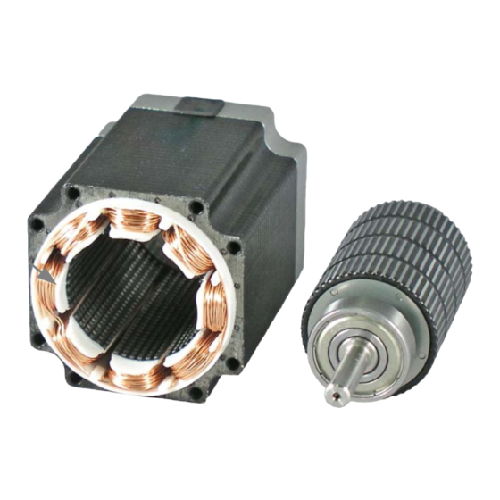
Stellaris® Stepper Motor Reference Design Kit Overview Motor Technology Introduction to Stepper Motors Stepper motors are synchronous DC motors which rotate in precise increments as their coils are energized. Stepper motors typically have step angles of 0.9°, 1.8°, 7.5°, or 15°. The motor in the RDK has a step angle of 1.8°... -
Page 11: Chopper Control
Stellaris® Stepper Motor RDK User’s Manual Figure 1-2. Stepper Speed-Torque Curve The Stepper RDK operates bipolar stepper motors with two coils—probably the most common class of stepper motor. Bipolar refers to the fact that the stepping sequence requires coil current to flow in alternating directions. -
Page 12: Rdk Specifications
Stellaris® Stepper Motor Reference Design Kit Overview RDK Specifications This reference design meets the following specifications. Electrical Supported motor type: Bipolar stepper Motor current (rated current per coil): 3 Amps Motor voltage (continuous coil voltage): 1-80 V Supply Voltage: 9-80 V Mechanical 4.6"... -
Page 13: Chapter 2: User Interfaces
The Stepper RDK firmware provides control of the stepper motor. It makes use of many of the features of the Stellaris microcontroller to perform the stepping function, reducing the number of external parts needed. In addition, the stepping firmware can be integrated with the user’s application, eliminating the need for separate microcontrollers for the stepping and application functions. -
Page 14: Speed Mode
User Interfaces The on-board user interface can operate in two modes: Speed mode and Position mode. In Speed mode, the motor runs continuously at a speed and direction that can be controlled by the user. In Position mode, the motor runs to a position controlled by the user. The starting mode is Speed mode. -
Page 15: Graphical User Interface
Stellaris® Stepper Motor RDK User’s Manual Graphical User Interface The stepper motor RDK board can be controlled from a graphical user interface (GUI) program running on a PC. Using the GUI provides much greater control of the motor than the on-board interface. -
Page 16: Table 2-1. Description Of Gui Main Window Controls
User Interfaces Table 2-1. Description of GUI Main Window Controls Item No. Name Description Speed and Status Area Target Sets the motor running speed in steps per second. The desired speed can be typed into the box. If the motor is already running, it changes speed to match. - Page 17 Stellaris® Stepper Motor RDK User’s Manual Table 2-1. Description of GUI Main Window Controls (Continued) Item No. Name Description GUI Main Window Buttons Run button Enables the stepper motor for running. The stepper motor must be enabled before it can be used. The motor does not move immediately when the Run button is pressed.
-
Page 18: File Menu
User Interfaces File Menu The File menu can be used to help manage the parameters. The following menu items are available: Load Parameters from Flash: The adjustable parameters that control the motor operation may be stored in flash memory in the RDK microcontroller. This menu choice commands the target to copy the parameters that were found in flash, into the active memory. -
Page 19: Table 2-2. Description Of Configuration Controls
Stellaris® Stepper Motor RDK User’s Manual Figure 2-3. Configuration Window Table 2-2. Description of Configuration Controls Item No. Name Description Control Mode Open-loop PWM In Open-loop PWM control mode, the firmware sets the PWM duty cycle to a value that corresponds to the desired current. The duty cycle is calculated based on the winding resistance and the bus voltage. - Page 20 User Interfaces Table 2-2. Description of Configuration Controls (Continued) Item No. Name Description Fixed Rise Time This value is used when Open-loop PWM control mode is chosen. (cont.) This value controls the amount of time that the winding is left turned on at the beginning of a step, before PWM is used to control the current in the winding.
-
Page 21: Chapter 3: Hardware Description
C H A P T E R 3 Hardware Description Key components in the reference design include a Stellaris LM3S617 microcontroller with an ARM Cortex-M3 core and a power stage consisting of Fairchild Semiconductor’s gate drivers and MOSFETs. Other complementary components complete the design by providing protection, signal acquisition, and power supply functions. -
Page 22: Block Diagram
See Appendix B, “Schematics” starting on page 33 for more details. Microcontroller (Schematic Pages 1-2) At the core of the Stepper Motor RDK is a Stellaris LM3S617 microcontroller. This part has a peripheral set optimized for motor control, including 6 high-speed ADC channels, a motor control PWM block, and an analog comparator. -
Page 23: Output Power Stage (Schematic
Stellaris® Stepper Motor RDK User’s Manual Also on this page are several LED status indicators, a simple reset circuit, and on-board user interface. The speed/position potentiometer's value is read by the microcontroller's ADC. Because the ADC's input span is 0-3 V, a resistor (R14) is used to pad the potentiometer voltage. -
Page 24: Control Interfaces (Schematic
Hardware Description Control Interfaces (Schematic Page 4) The Stepper RDK has three power supply rails. The input power source is used directly to provide motor power and has a wide operating range. The exact supply voltage is not critical because the chopper control maintains constant motor current. -
Page 25: Figure 3-3. Chopper Waveform Generation
Stellaris® Stepper Motor RDK User’s Manual Figure 3-3. Chopper Waveform Generation Blanking Blanking Time Time High-side MOSFET ON Control Signal to Gate Driver Low-side MOSFET ON Sampling Current Threshold Motor Winding Current (Amps) Start of step Chopping continues to end of step A summary of the current control software is shown in Figure 3-4. -
Page 26: Parameter Reference
Hardware Description In addition to eliminating a dedicated chopper control IC, software-based chopper control makes it possible to easily change the current set-point. As an example, the RDK GUI has several parameters that change chopper control behavior for motors and loads that have differing characteristics. -
Page 27: Appendix A: Parameters
A P P E N D I X A Parameters Table A-1 provides a summary of all configuration parameters. See “Parameter Descriptions” on page 27 for more information. Table A-1. Parameter Configuration Summary Parameter Name Units Range Default Motor Running Configuration Parameters Target Position PARAM_TARGET_POS whole... -
Page 28: Motor Running Configuration
Motor Running Configuration Target Position Units Range Default PARAM_TARGET_POS whole steps -8388608–8388607 This parameter indicates the target position which is represented internally as a signed 24-bit number. It starts at position 0 and can run to the positive maximum or negative minimum of the range. -
Page 29: Deceleration
Stellaris® Stepper Motor RDK User’s Manual Deceleration Units Range Default PARAM_DECEL steps/sec 100–60000 60000 This parameter is the rate at which the motor decelerates from the target speed to stop at the target position. Typically, the motor can decelerate faster than accelerate since the load and friction are working to help decelerate the motor. -
Page 30: Drive Current
Drive Current Units Range Default PARAM_DRIVE_CURRENT 100–3000 1500 This parameter sets the current level in the winding when the motor is running. If the Chopper mode is used, then the chopper switches the voltage to the winding off and on in order to maintain this current level. -
Page 31: Decay Mode
Stellaris® Stepper Motor RDK User’s Manual Closed-loop PWM mode combines the features of Chopper and Open-loop PWM modes. Closed loop PWM mode uses a programmed PWM duty cycle to set the current. However, the current is also measured each time a PWM pulse is applied, and the duty cycle is adjusted to compensate for variation in the measured current compared to desired drive current. - Page 32 November 4, 2009...
- Page 33 A P P E N D I X B Schematics This section contains the schematics for the LM3S1968 Evaluation Board: Contents Page on page 34 Microcontroller on page 35 Driver - Coil A on page 36 Driver - Coil B on page 37 Power Supplies and USB on page 38 November 4, 2009...
- Page 34 Contents Page History Revision Date Description U_Stepper Microcontroller U_Stepper Ph A Drive Jan 17, 07 First Full Release Stepper Microcontroller.SchDoc Stepper Ph A Drive.SchDoc Feb 07, 07 Change USB device to bus power. Feb 09, 07 First Production Revision Jul 10, 07 Change C18, C19, C31, C32 to no-populate U_Stepper Ph B Drive U_Stepper Power Supplies...
- Page 35 Microcontroller FAULT +3.3V Mode Push Button SWUSR VCP_RX PA0/U0Rx PB0/PWM2 PH_B1 VCP_TX PA1/U0Tx PB1/PWM3 PH_B2 PA2/SSIClk SWUSR PA2/SSIClk PA3/SSIFss +3.3V PA3/SSIFss PB3/FAULT PA4/SSIRx SW-PB PA4/SSIRx PB4/C0- ISENSEAB PA5/SSITx PA5/SSITx PB5/C0o PB6/C0+ PB6/C0+ PB7/nTRST PB7/TRST TCK/SWCLK PC0/TCK/SWCLK PD0/PWM0 PH_A1 TMS/SWDIO LEDSTATUS PC1/TMS/SWDIO PD1/PWM1 PH_A2...
- Page 36 Driver - Coil A +15V 10uF VMOTOR 0.1UF S100 NOTES: Q1-8 Can subst FDMS3682 for lower Rds(on) OMIT 0.1UF PH_A1 Q1-8 Can subst FDS3672 in SOIC package 10uF FDMS3672 FDMS3672 0.1UF MOTOR_A1 DT/SDn MOTOR_A2 PH_A_ENn FDV310N 100PF FDMS3672 FDMS3672 FAN73832 +3.3V OMIT FAN4174IS5X_NL...
- Page 37 Schematic page 1 Driver - Coil B +15V 10uF VMOTOR 0.1UF S100 OMIT 0.1UF PH_B1 10uF FDMS3672 FDMS3672 0.1UF MOTOR_B1 DT/SDn MOTOR_B2 PH_B_ENn FDV310N 100PF FDMS3672 FDMS3672 FAN73832 +3.3V OMIT FAN4174IS5X_NL +15V I_PHB +3.3V 0.1UF 0.1 1W S100 OMIT PH_B2 10uF 0.1UF 100K...
- Page 38 Power Supplies and USB 10-80VDC POWER INPUT VMOTOR BLM21P221SG 0.01uF PJ-002BH-SMT 261K RON/SD 261K +3.3V 150UF 150UF S100 0.1uF VSENSE 100V 100V 0.1uF 0.01uF 100K 330uH 0 OHM 0.1uF DR127-331 BLM21P221SG S100 LM5008MM 10uF 1.0K 3.3V 300mA Switching Regulator USB MINI B RECEPTACLE +15V +3.3V OMIT...
- Page 39 A P P E N D I X C PCB Component Locations This section shows the PCB component locations for the Stepper Motor RDK. November 4, 2009...
- Page 40 Power Supplies and USB...
- Page 41 A P P E N D I X D Bill of Materials (BOM) This section provides the BOM for the Stepper Motor RDK. November 4, 2009...
- Page 42 Texas Instruments Edison Project Stepper Motor Reference Design Kit Rev A Issue 3 6/10/07 Bill Of Materials Item Qty Part Number Description C1, C10, C23, C0805C105Z4VACTU Capacitor 1uF 16V Y5V 0805 Kemet C35, C39, C52 C11, C12, C24, Capacitor 100pF 50V 10% Ceramic 0805...
- Page 43 Stellaris® Stepper Motor RDK User’s Manual Resistor 150K 1% 0805 Generic Resistor 340 Ohms 1% 0805 Generic Resistor Zero Ohm 5% 0805 Generic R27, R42 LR2512-LF-R100-F Resistor 0.1 Ohms 2W 2512 SW1, SW2 B3S-1000 Switch, Momentary Tact SMT Omron LM3S617-CQN25...
- Page 44 November 4, 2009...
- Page 45 IMPORTANT NOTICE Texas Instruments Incorporated and its subsidiaries (TI) reserve the right to make corrections, modifications, enhancements, improvements, and other changes to its products and services at any time and to discontinue any product or service without notice. Customers should obtain the latest relevant information before placing orders and should verify that such information is current and complete.
Need help?
Do you have a question about the Stellaris and is the answer not in the manual?
Questions and answers