Lifetime 9594 Assembly Instructions Manual
Backboard & rim combo mounting kit
Hide thumbs
Also See for 9594:
- Assembly instructions manual (76 pages) ,
- Assembly instructions and owner's manual (19 pages) ,
- Assembly instructions manual (24 pages)
Table of Contents
Advertisement
Quick Links
BACKBOARD & RIM COMBO
MOUNTING KIT
MODEL 9594
BEFORE ASSEMBLY:
• There are three ways to install this mounting kit: to a
pole, a roof or a wall. Follow the instructions carefully
to successfully complete the assembly. You should
only use two of the instructional sections:
1. Combo assembly, sections 1, 2 or 3, depending on your combo, i.e.,
Impact™, Fusion™ or metal-framed backboard
2. 9594 kit assembly and installation, sections 4, 5 or 6, depending on
your installation type, i.e., to a pole, a roof or a wall
You will also use the Parts Identifi er pages
The Parts Identifi er , located at the center of this manual,
consists of four yellow pages displaying all the
parts and hardware included with both the 9594
kit and the purchased backboard & rim combo. It
can be removed from these instructions and used
as a quick reference throughout the assembly and
installation. Use the Parts Identifi er to verify that all
parts and hardware are included and in working
order.
• At least 3 adults are recommended for setup.
SAVE THIS INSTRUCTION IN THE EVENT THAT THE MANUFACTURER HAS TO BE CONTACTED FOR REPLACEMENT PARTS.
TOOLS REQUIRED
7/16" (≈11 mm)
TOOLS REQUIRED
(x2)
3/4" (≈19 mm)
(x2)
(x1)
(x1)
There are three installation options. The installer is responsible for selecting mounting hardware
suitable for a roof or wall mount option.
QUESTIONS?
CONTACT LIFETIME CUSTOMER SERVICE:
Dial 1-800-225-3865
7:00 am-5:00 pm (M-F) MST
and 9:00 am-1:00 pm (Sat) MST
1/2" (≈13 mm)
(x1)
3/8" (≈10 mm)
(x1)
(x1)
(x3)
Live Chat:
www.lifetime.com/customerservice
(Click on the "LIVE CHAT" tab)
ASSEMBLY INSTRUCTIONS
Pole Mount
Wall Mount
9/16" (≈14 mm)
(x2)
1/2" (≈13 mm)
(x1)
(x3)
(x1)
For Customer Service in Mainland Europe and
the United Kingdom,
E-mail: cs@lifetimeproducts.eu
1
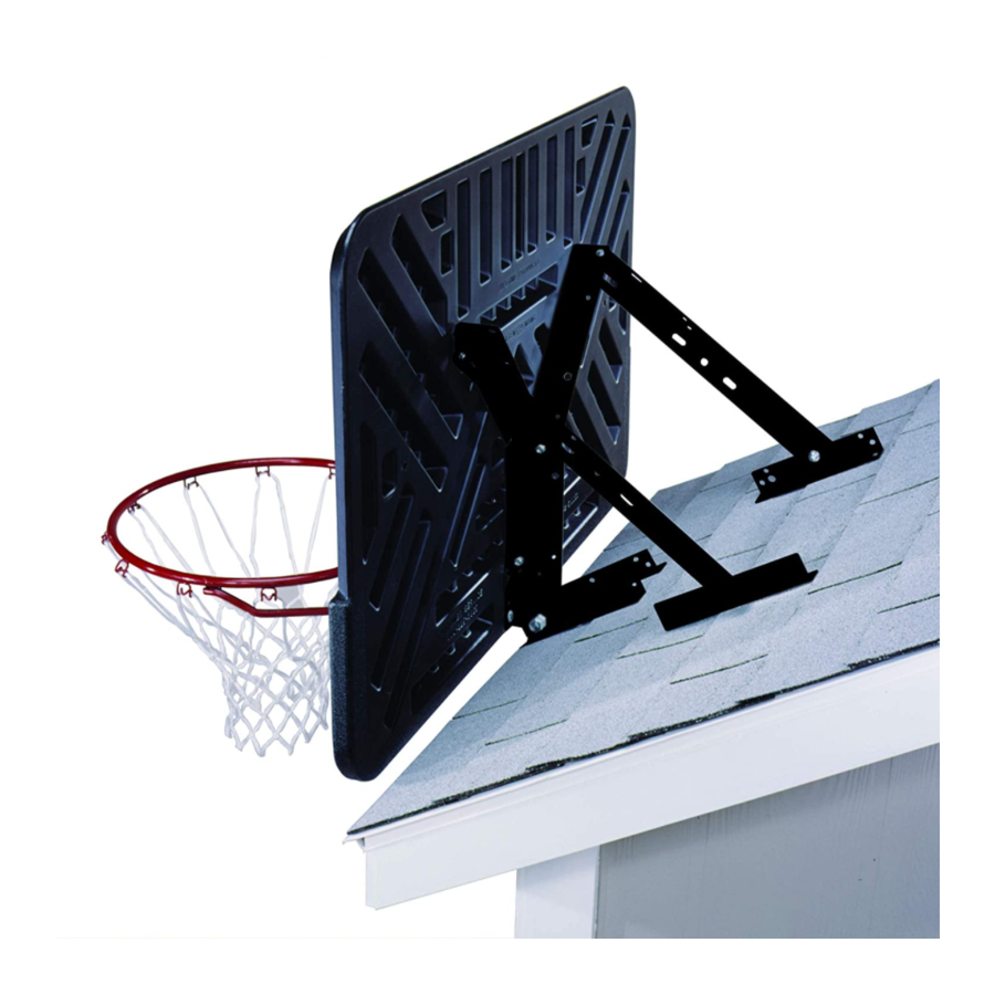
Roof Mount
TABLE OF CONTENTS
Icon Legend..................................................................2
Warnings & Notices......................................................3
What to Expect............................................................4
Impact™ Backboard & Rim Assembly.........................5
Fusion™ Backboard & Rim Assembly.........................12
Steel-Framed Backboard & Rim Assembly..................20
Pole-Mount Assembly................................................33
Roof-Mount Assembly................................................38
Wall-Mount Assembly................................................43
Registration.......................................................50
Warranty..........................................................51
Model Number: 9594
Product ID:
Advertisement
Table of Contents

Related Manuals for Lifetime 9594


Summary of Contents for Lifetime 9594
-
Page 1: Table Of Contents
Impact™, Fusion™ or metal-framed backboard Pole Mount 2. 9594 kit assembly and installation, sections 4, 5 or 6, depending on your installation type, i.e., to a pole, a roof or a wall You will also use the Parts Identifi er pages The Parts Identifi... -
Page 2: Icon Legend
ICON LEGEND • Indicates special heed should be taken when reading. • Indicates the parts to be used for a section. • Indicates no parts required for a specifi c section. • Indicates the hardware to be used for a section. •... -
Page 3: Warnings & Notices
WARNINGS & NOTICES SAFETY INSTRUCTIONS FAILURE TO FOLLOW THESE WARNINGS MAY RESULT IN SERIOUS INJURY OR PROPERTY DAMAGE AND WILL VOID WARRANTY. Owner must ensure that all players know and follow these rules for safe operation of the system. To ensure safety, do not attempt to assemble this product without following the instructions carefully. Check entire box and inside all packing material for parts and/or additional instruction material. -
Page 4: What To Expect
WHAT TO EXPECT This set of instructions explains not only how to assemble and mount the 9594 kit to a pole, roof or wall but also explains how to assemble and mount Lifetime’s backboard & rim combo models that can go with it. Lifetime has many models but only three types of backboards: 1. -
Page 5: Impact™ Backboard & Rim Assembly
BNP (x1) • Unless instructed otherwise, use the U-bolt that came with your purchased backboard and rim combo. For model 90718 only: use the U-bolt that came with this 9594 mounting kit. DZS (x2) • Needed only for a roof installation HARDWARE BAG FOR IMPACT™... - Page 6 9594 KIT PARTS: COMBO KIT PARTS: AOX (x1) ESF (x2) More parts come with the 9594 kit, but only the parts used in this section are shown here. COMBO KIT IMPACT™ BACKBOARD FROM MODELS 3823 AND 90703 AJI (x1) TOOLS REQUIRED 7/16"...
- Page 7 SECTION 1 (CONTINUED) TOOLS AND HARDWARE REQUIRED • Use the U-bolt included with your purchased backboard and rim combo. (x1) APK (x1) • IMPORTANT: USE THE U-BOLT THAT CAME WITH YOUR PURCHASED BACKBOARD AND RIM COMBO. Using the U-bolt that came with your backboard & rim combo, insert the U-bolt (APK) through the holes in the backboard brackets (ESF) as indicated.
- Page 8 SECTION 1 (CONTINUED) TOOLS AND HARDWARE REQUIRED 7/16" (≈11 mm) (x2) AAS (x2) ABS (x2) AAB (x2) (x1) • Position the spacers (ABS) between the backboard brackets, ensuring they are aligned with the correct holes in the brackets. Slide a hex bolt (AAS) through the brackets and each spacer, and secure them with centerlock nuts (AAB). Now let’s attach these backboard brackets to the backboard and rim combo.
- Page 9 SECTION 1 (CONTINUED) TOOLS AND HARDWARE REQUIRED 1/2" (≈13 mm) (x1) APN (x2) ABD (x2) (x2) IMPACT™ BACKBOARD-TO-RIM-AND-BACKBOARD-BRACKETS ASSEMBLY • Set the backboard brackets from steps 1.1–1.2 onto the back of the Impact™ backboard (AJI) with the U-bolt through the backboard as shown.
- Page 10 SECTION 1 (CONTINUED) TOOLS AND HARDWARE REQUIRED 1/2" (≈13 mm) (x2) AAC (x2) APN (x2) ABD (x2) (x2) • Now, secure the backboard brackets to the backboard using the hardware indicated. Ensure the support channel (AOX) was inserted into the slot in the backboard in step 1.4.
- Page 11 • Needed only for a roof installation (x2) 1.6a 1.6b • If you are installing kit 9594 to a roof, follow this • If you are installing kit 9594 to a pole or wall, step (1.6a): follow this step (1.6b): •...
-
Page 12: Fusion™ Backboard & Rim Assembly
U-bolt that came with this 9594 mounting kit. PARTS REQUIRED 9594 PARTS: COMBO KIT PARTS: ESF (x2) More parts come with the 9594 kit, but only the parts used in this section are shown here. AOX (x1) ALX (x1) - Page 13 FUSION™ BACKBOARD & RIM ASSEMBLY PARTS REQUIRED COMBO KIT FUSION™ BACKBOARDS FROM MODELS 90086, 73650 AND 73621 AJI (x1) AJI (x1) TOOLS REQUIRED 7/16" (≈11 mm) 1/2" (≈13 mm) 3/8" (≈10 mm) (x2) (x1) (x2) (x1) (x1)
- Page 14 SECTION 2 (CONTINUED) TOOLS AND HARDWARE REQUIRED (x1) • Use the U-bolt that came with your purchased backboard and rim combo. BNP (x1) IMPORTANT: USE THE U-BOLT THAT CAME WITH YOUR PURCHASED BACKBOARD AND RIM COMBO. • Insert the U-bolt (BNP) through the holes in the backboard brackets (ESF) as indicated. •...
- Page 15 Slide a hex bolt (AAS) through the brackets and each spacer, and secure them with centerlock nuts (AAB). Now let’s attach these backboard brackets to the Lifetime® backboard & rim combo. • These nuts are centerlock nuts. They are designed to be tight; therefore, they will be harder to tighten. Tighten until the spacers are fl ush with...
- Page 16 FUSION™ BACKBOARD-TO-RIM ASSEMBLY • Lifetime® off ers two types of Fusion™ backboards (AJI). They are similar. They just look slightly diff erent. The fi rst has squared corners (Fig. 1), while the second has rounded corners (Fig. 2). Both assemble in the same way. Only the backboard with squared corners is shown in the assembly in this section.
- Page 17 SECTION 2 (CONTINUED) TOOLS AND HARDWARE REQUIRED 1/2" (≈13 mm) (x1) (x2) ABK (x2) • Lay the backboard face down over a table or box. Insert the U-bolt on the backboard brackets down through the two upper holes in the backboard and rim while inserting the two bolts on the rim up through the two lower holes in the backboard, the rim support channel (AOX) and the backboard brackets as shown.
- Page 18 2.7a • If you are installing kit 9594 to a roof, follow this step (2.7a). If not, go to step 2.7b. • Attach backboard brackets and angle braces (DZS) to the backboard using screws (ADQ). Leave both braces loose until instructed. Set the assembly aside.
- Page 19 2.7b • If you are installing kit 9594 to a pole or wall, follow this step (2.7b). If not, go back to step 2.7a. • Align the holes in the ends of the backboard brackets with those in the backboard and secure the brackets to the backboard using two screws (ADQ).
-
Page 20: Steel-Framed Backboard & Rim Assembly
25% of actual size • Unless instructed otherwise, use the U-bolt that came with your purchased backboard and rim combo. For model 90718 only: use the U-bolt that came with this 9594 mounting kit. BACKBOARD & RIM COMBO HARDWARE REQUIRED... - Page 21 ABF (x2) ABD (x2) ABG (x2) ACS (x2) BNP (x1) AJW (x2) 25% of actual size A0W (x1) 25% of actual size 25% of actual size • For model 90718, use the U-bolt that came with the 9594 mounting kit.
- Page 22 BACKBOARD FROM MODELS 79910, 73729, 71526, 90087, 90010 AND 90718 ESF (x2) More parts come with the 9594 kit, but only the parts used in this section are shown here. METAL PARTS AJI (x1) Corner guards and frame pads not shown...
- Page 23 SECTION 3 (CONTINUED) TOOLS AND HARDWARE REQUIRED • Use the U-bolt included with your purchased backboard and rim combo. (x1) BNP (x1) • IMPORTANT: USE THE U-BOLT THAT CAME WITH YOUR PURCHASED BACKBOARD AND RIM COMBO. Insert the U-bolt (BNP) through the holes in the backboard brackets (ESF) as indicated. •...
- Page 24 SECTION 3 (CONTINUED) TOOLS AND HARDWARE REQUIRED 7/16" (≈11 mm) (x2) AAS (x2) ABS (x2) AAB (x2) (x1) • Position the spacers (ABS) between the backboard brackets (ESF), ensuring they are aligned with the correct holes in the brackets. Slide a hex bolt (AAS) through the brackets and each spacer, and secure them with centerlock nuts (AAB). Now let’s attach these backboard brackets to the backboard and rim combo.
- Page 25 SECTION 3 (CONTINUED) TOOLS AND HARDWARE REQUIRED 1/2" (≈13 mm) (x1) ABQ (x1) ABF (x2) ABD (x2) (x1) ABG (x2) AAR (x2) AAQ (x1) METAL-FRAMED BACKBOARD-TO-RIM-AND-BACKBOARD BRACKETS ASSEMBLY Metal-frame backboard—will have one of two types of rims: Slam-it or Slam-it ®...
- Page 26 SECTION 3 (CONTINUED) TOOLS AND HARDWARE REQUIRED 1/2" (≈13 mm) (x1) AAJ (x2) (x1) • Slide the pivot assembly into the housing of the Slam-It Pro rim (ALX) and align the holes as indicated. ® • Slam-It • Slam-It Pro Rim ™...
- Page 27 PARTS IDENTIFIER (FIND YOUR RIM AND BACKBOARD TYPES) PARTS REQUIRED METAL BACKBOARD & RIM PARTS METAL-FRAMED BACKBOARD ALX (x1) ALX (x1) AJI (x1) AOX (x1) APY (x1) AMA (x1) PLASTIC BACKBOARD & RIM PARTS AJQ (x1) IMPACT™ BACKBOARD ALD (x1) BAA (x1) BAB (x1) AJI (x1)
- Page 28 PARTS IDENTIFIER (YOU WON’T USE EVERY PIECE—ONLY THOSE REQUIRED FOR YOUR MOUNT TYPE) KIT PARTS & HARDWARE REQUIRED (YOU WON”T USE EVERY PART—ONLY THOSE REQUIRED FOR YOUR MOUNT TYPE) KIT 9594 PARTS ESJ (x4) ESI (x2) ESF (x2) ESA (x2)
-
Page 29: Parts Identifier
PARTS IDENTIFIER BACKBOARD & RIM COMBO HARDWARE REQUIRED (FIND YOUR MODEL) HARDWARE BAG FROM IMPACT™ MODELS 3823 AND 90703 APJ (x2) AAC (x2) APK (x1) APN (x4) AAJ (x2) ABD (x4) HARDWARE BAG FROM FUSION™ MODELS 90086, 73650 AND 73621 AJW (x2) * Not to scale ABK (x4) - Page 30 ABF (x2) ABD (x2) ACS (x2) ABG (x2) BNP (x1) 25% of actual size AJW (x2) A0W (x1) 25% of actual size 25% of actual size • Use the U-bolt that came with the 9594 mounting kit. See page i.
- Page 31 SECTION 3 (CONTINUED) TOOLS AND HARDWARE REQUIRED 1/2" (≈13 mm) (x1) (x1) AAQ (x1) • Use the 1/2" (≈13 mm) socket to press the second push nut (AAQ) 1/4" (≈6,4 mm) onto the other end of the axle to lock the pin in place.
- Page 32 SECTION 3 (CONTINUED) TOOLS AND HARDWARE REQUIRED 1/2" (≈13 mm) (x1) ACS (x2) ABK (x2) ABC (x2) (x2) 3.10 • The Slam-It™ and Slam-It™ Pro rims connect to the backboard in the same way. Lay the backboard on a table or bench. Insert the U-bolt through the two upper openings on the backside of the backboard, down through the holes in the fi...
- Page 33 ™ ™ 3.12b If you are installing kit 9594 to a pole or wall, follow this step (3.12b): • • Secure the backboard brackets to the backboard at the locations indicated using the hardware provided. DO NOT use an angle brace if you are not installing this system to your roof.
- Page 34 SECTION 3 (CONTINUED) TOOLS AND HARDWARE REQUIRED 1/2" (≈13 mm) (x1) AOW (x1) ADR (x4) ABK (x2) AAV (x2) AJW (x2) (x2) 3.13 • Thread the two jam nuts (AAV) over the two ends of the U-bolt as far as they will go. Set a spring (AJW) over each end of the U-Bolt.
- Page 35 SECTION 3 (CONTINUED) TOOLS AND HARDWARE REQUIRED ADP (x4) (x1) 3.15 • Peel the plastic fi lm off the front of the backboard. • Slam-It • Slam-It Pro Rim ™ ™ SOME MODELS INCLUDE CORNER GUARDS SOME MODELS INCLUDE FRAME PADS 3.16 •...
- Page 36 SECTION 3 (CONTINUED) TOOLS AND HARDWARE REQUIRED ADP (x6) (x1) 3.17 • If your combo comes with corner guards, they’ve come pre-installed. • Secure the left and right corner frame pads (BAA and BAB) to the bottom of the frame, overlapping the center frame pad. They will overlap the center frame pad.
-
Page 37: Pole-Mount Assembly
• Section 4 is for mounting a backboard and rim combo to an existing 3 1/2" (≈8,9 cm) round pole. If this is your goal, you’ve come to the right place. The following steps show just how to do this. 9594 Mounting Kit Assembly for Poles... - Page 38 KIT 9594 HARDWARE APJ (x4) ETB (x2) APN (x4) AAA (x4) ABD (x4) CZY (x2) AAX (x2) PARTS REQUIRED KIT 9594 METAL PARTS ESA (x2) ESH (x4) ESI (x2) CZZ (x2) TOOLS REQUIRED 1/2" (≈13 mm) 9/16" (≈14 mm) 3/4" (≈19 mm)
- Page 39 SECTION 4 (CONTINUED) TOOLS AND HARDWARE REQUIRED 1/2" (≈13 mm) (x2) APJ (x2) (x2) 9/16" (≈14 mm) ETB (x2) (x2) (x2) AAA (x4) APN (x2) ABD (x2) (x1) • Make a mark on the pole 115 3/4" (≈294 cm) from the ground.
- Page 40 SECTION 4 (CONTINUED) TOOLS AND HARDWARE REQUIRED 1/2" (≈13 mm) (x2) (x2) APJ (x2) ABD (x2) APN (x2) • Place an extension bracket (ESH) at the top of a pole mount bracket. While holding the extension bracket in place, place the end of a diagonal support (ESI) next to the extension bracket so the smaller hole in the support aligns with the lower hole in the bracket as indicated.
- Page 41 SECTION 4 (CONTINUED) TOOLS AND HARDWARE REQUIRED 3/4" (≈19 mm) (x2) (x3) CZY (x2) AAX (x2) In this example, we’re mounting a Fusion™ backboard & rim combo to a pole; however, all backboard & rim combos mount to a pole in the same way. •...
-
Page 42: Roof-Mount Assembly
• Section 5 is for mounting a backboard and rim combo to a roof. If this is your goal, you’ve come to the right place. The following instructions show just how to do this. 9594 Mounting Kit Assembly for Rooves... - Page 43 ROOF-MOUNT ASSEMBLY HARDWARE REQUIRED KIT 9594 HARDWARE CZY (x1) AAX (x1) APJ (x4) APN (x4) ABD (x4) PARTS REQUIRED KIT 9594 METAL PARTS ESH (x4) ESG (x2) TOOLS REQUIRED 1/2" (≈13 mm) 3/4" (≈19 mm) (x1) (x2) (x2) (x3) (x2)
- Page 44 SECTION 5 (CONTINUED) TOOLS AND HARDWARE REQUIRED (x1) (x1) (x1) (x1) • Place two extension brackets (ESH) 2 1/2" (6,35 cm) apart on the edge of the roof. The ends of the brackets with the larger holes should be along the edge of the roof as indicated. Secure the brackets to the roof, at the locations indicated, with hardware (not included) appropriate for use on a roof.
- Page 45 SECTION 5 (CONTINUED) TOOLS AND HARDWARE REQUIRED 3/4" (≈19 mm) (x2) (x2) CZY (x1) (x3) AAX (x1) In this example, we’re mounting a Fusion™ backboard & rim combo to a roof; however, all backboard & rim combos mount to a roof in the same way. •...
- Page 46 SECTION 5 (CONTINUED) TOOLS AND HARDWARE REQUIRED 1/2" (≈13 mm) (x2) (x2) APJ (x4) APN (x4) (x3) ABD (x4) • Attach through the long slots in the stud brackets (ESG) to the upper angle braces (attached in step 1.5a, 2.7a, or 3.12a) on each backboard bracket with a hex bolt (APJ), a fl...
-
Page 47: Wall-Mount Assembly
WALL-MOUNT ASSEMBLY • Section 6 is for mounting a backboard and rim combo to a wall. If this is your goal, you’ve come to the right place. The following instructions show just how to do this. - Page 48 WALL-MOUNT ASSEMBLY HARDWARE REQUIRED KIT 9594 HARDWARE APJ (x14) CZY (x2) APN (x14) ABD (x14) AAX (x2) PARTS REQUIRED KIT 9594 METAL PARTS ESJ (x4) ESG (x2) ESI (x2) ESH (x4) TOOLS REQUIRED (x1) 1/2" (≈13 mm) 3/4" (≈19 mm)
- Page 49 SECTION 6 (CONTINUED) TOOLS AND HARDWARE REQUIRED (x2) (x1) (x2) • Locate and mark two adjacent studs in the wall where you would like the backboard to hang. For the rim to be at regulation height, draw a horizontal line 115 5/8" (293,68 cm) from the ground. Measure up 8" (20,32 cm) from the 115 5/8" (293,68 cm) line and draw another horizontal line parallel to the fi rst.
- Page 50 SECTION 6 (CONTINUED) TOOLS AND HARDWARE REQUIRED 1/2" (≈13 mm) (x2) APJ (x4) (x2) APN (x4) ABD (x4) (x2) • Place the four (4) extension brackets (ESH) to the stud brackets (ESG) and align the holes indicated. Secure the ends of the extension brackets to the stud brackets.
- Page 51 SECTION 6 (CONTINUED) TOOLS AND HARDWARE REQUIRED 1/2" (≈13 mm) (x2) (x1) APJ (x12) APN (x12) ABD (x12) (x1) • Attach both diagonal supports (ESI) to the upper extension • Attach the four stabilizers (ESJ) to the extension brackets brackets with hex bolts (APJ), fl...
- Page 52 SECTION 6 (CONTINUED) TOOLS AND HARDWARE REQUIRED 3/4" (≈19 mm) (x2) (x3) CZY (x2) (x3) AAX (x2) THREE PEOPLE ARE NECESSARY FOR THIS STEP In this example, we’re mounting a Fusion™ backboard & rim combo to a wall; however, all backboard & rim combos mount to a wall in the same way. •...
- Page 53 NOTES...
-
Page 54: Registration
. And you can rest assured that Lifetime will not sell or provide your personal ® ® data to other third parties, or allow them to use your personal data for their own purposes. We invite you to read our privacy policy at www.lifetime.com REGISTER today! -
Page 55: Warranty
2. This warranty is nontransferable and is expressly limited to the repair or replacement of defective product. If the product is defective within the terms of this warranty, Lifetime Products, Inc. will repair or replace defective parts at no cost to the purchaser. - Page 56 ® ENHANCE YOUR LIFETIME PURCHASE BY ADDING ACCESSORIES OR OTHER GREAT PRODUCTS To purchase accessories or other Lifetime products, visit us at: ® www.lifetime.com Or call: 1-800-424-3865 7:00 am–5:00 pm (M–F) MST and 9:00 am–1:00 pm Saturday MST www.lifetime.com 9/01/2022...
Need help?
Do you have a question about the 9594 and is the answer not in the manual?
Questions and answers