Table of Contents
Advertisement
Quick Links
WHAT TO DO IF YOU SMELL GAS:
• Do not try to light any appliance
• Do not touch any electric switch; do not use any
phone in your building
• Immediately call your gas supplier from a
neighbor's phone. Follow the gas supplier's
instructions.
• If you can not reach your gas supplier call the fire
department
• Installation and service must be performed by a
qualified licensed installer, service agency or the
gas supplier.
Manufactured by:
SAINT ROCH S.R.L
ITALY
Saint Roch Universal Boiler
Boiler Manual And Installation
Instructions for Atmospheric Venting
(See Direct Venting addendum for Direct Vent installation)
Danger
3-6 Section Boilers
Please Read Instructions Carefully
Save for Future Reference
If the information in this
manual is not followed
exactly, a fire or explosion
may result causing property
damage, personal injury or
loss of life.
Distributed By:
QHT, INC.
3560 LAFAYETTE ROAD
BLDG. 2, UNIT A
PORTSMOUTH, NH 03801
PHONE: 603-334-6400 FAX: 603-334-6401
Conforms to UL Std. 726
WARNING
REV. 622
Advertisement
Table of Contents

Related Manuals for Saint Roch Universal SRU Series

Summary of Contents for Saint Roch Universal SRU Series
- Page 1 Saint Roch Universal Boiler 3-6 Section Boilers Boiler Manual And Installation Instructions for Atmospheric Venting (See Direct Venting addendum for Direct Vent installation) Please Read Instructions Carefully Save for Future Reference Conforms to UL Std. 726 Danger WARNING WHAT TO DO IF YOU SMELL GAS: If the information in this •...
- Page 2 DHW, making it truly UNIVERSAL. Saint Roch’s new SRU series boilers are lighter, contain less water and are stronger than other tankless boilers. The Hydrolevel 3250TC “Fuel Smart” controller is designed to work in conjunction with the DHW coil in the boiler and your space heat zones.
-
Page 3: Table Of Contents
Table of Contents Section Page Important Information and Warnings Homeowner Information For Gas General Information Boiler Block Assembly Boiler Location Installation of Boiler Trim Kit 10,11 Components Tankless Coil Installation 12,13 Piping The Boiler Intake Venting 15,16 Exhaust Venting Common Exhaust Venting Gas Venting Burner Setup Oil Burner Setup... - Page 4 WARNING IMPORTANT INFORMATION Please read this page carefully. Homeowner: Service Technician: • For homeowner or person responsible • For a qualified service technician who for simple start-up and routine has the necessary equipment to check maintenance of the system. Instructions the boiler and system performance, and must be followed to assure proper is responsible for start-up and service of...
- Page 5 WARNING IMPORTANT INFORMATION Please read this page carefully. DANGER CAUTION IMPORTANT Increasing the thermostat setting above the RISK OF SCALDING. Hot water will cause pre-set temperature may cause severe burns third degree burns in 6 seconds at 60°C and consume excessive energy. Hotter water (140°F), in 30 seconds at 54°C(130°F).
-
Page 6: Homeowner Information For Gas
HOMEOWNER INFORMATION FOR GAS TO START UP THE APPLIANCE STOP! Read the safety information on the side of the boiler. DO NOT START THE BOILER UNLESS ALL CLEANOUT DOORS ARE SECURED AND SEALED. (Skip to step 9 for oil burning boilers) 2. -
Page 7: General Information 1
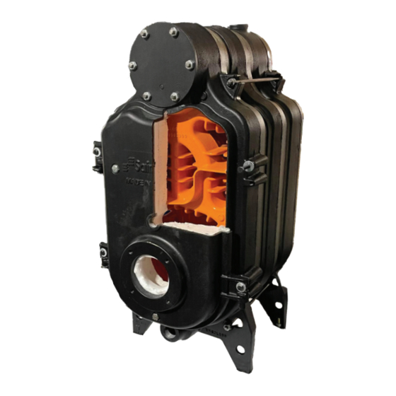
1. General Information The SRU series boilers are wet base design, sectional, cast-iron boilers for forced hot water heating systems. The boilers are shipped pre-assembled from the factory in lengths from three to six sections. They are designed for firing with oil or gas power burners, which are packed separately along with the jacket and controls for shipping purposes. -
Page 8: Boiler Block Assembly
2. Boiler Block Assembly All SRU series boilers are shipped from the factory in assembled boiler blocks. Boiler Block Assembly: 10. Plug gasket 18. 3/4" Plug (Sight Hole) Front Section 11. 1/4" X 1 1/4" Bushing 19. Boiler Door Hinge (4 Rear Section 12. -
Page 9: Boiler Location
3. Boiler location The following are the minimum clearances to construction or combustible materials: 9” TOP 24” Standard Installation Clearances Above Front Sides Rear Chimney Below 12” 24” Connector 9” FRONT 9” 24” 12” 9” 2” 9” SIDE 2” 9” Combustible REAR DANGER... -
Page 10: Installation Of Boiler Trim Kit Components
4. Installation of Boiler Trim Components Trim Kit Components WT-1 and WT-2 Trim Kits Include: 1 - Hydrostat 3250TC High Limit w/LWCO 1 – ¾” Plugs 1 – Combo pressure/temp gauge 1 – ¾” 90° Elbow 1 – ¾” X 3” Nipple 1 –... - Page 11 4. Installation of Boiler Trim Components (Continued..) 1. For the SRU LT “less Tankless” boiler, Install Hydrolevel 3250Plus Electrowell in upper left or right rear 3/4” tappings. For SRU with Coil, Use the 3/4” tapping on the front coil plate. All tapings and joints should be sealed with piping compound. The boiler high limit can be adjusted up to 200o F, and should be set to the desired temperature by the installer.
-
Page 12: Tankless Coil Installation
5. Tankless Coil Installation DANGER-SCALD HAZARD The control supplied with this boiler is not intended to provide accurate control of the domestic water temperature leaving the tankless heater. An installer supplied, ASSE 1017 or ASSE 1070 certified tempering valve is therefore REQUIRED as part of this boiler’s installation. - Page 13 5. Tankless Coil Installation (Continued..) When Installing the coil: Use cross pattern tightening Using a 17mm Socket/wrench: Start to tighten at spot 1, then move to spot 2 and so on..DO NOT OVER TIGHTEN! NOTE: After boiler is warmed up to temperature, retighten the nuts in the same cross pattern.
-
Page 14: Piping The Boiler
6. Piping The Boiler All piping must conform to state and local codes. Page 11 shows the location and size of the boiler tappings. It is recommended to install unions and gate valves at the inlet and outlet of the boiler, so it may be readily isolated for service. A low water cut off is required if the boiler is installed above the level of radiation. -
Page 15: Intake Venting
7. Intake Venting 1. Be certain adequate air is available for combustion and ventilation. a.) Boiler located in unconfined space: Installation in large areas, such as basements, can usually be assumed to provide sufficient air. b.) Boiler located in confined space : (See Figure A. on page 14) If all air for combustion and ventilation is to come from within the building: Two (2) openings shall be provided with one (1) opening commencing within 12 inches of the ceiling and one (1) opening commencing within 12 inches of the floor of... - Page 16 7. Intake Venting (Continued...) c.) Boiler located in a room under negative pressure: If the boiler is to be installed within a home where the operation of exhaust fans, attic fans, kitchen ventilation systems, clothes dryers or fireplaces may create severe negative vent pressures causing unsatisfactory combustion and venting, special provisions should be made for additional make-up air to supply the other air requirements.
-
Page 17: Exhaust Venting
8. Exhaust Venting The SRU boiler is a high efficiency unit that requires proper venting. The boiler must be vented to the outdoors by means of a lined masonry or a approved pre- fabricated chimney of the size and height recommended by the manufacturer or by a listed "power venting"... -
Page 18: Common Exhaust Venting
8.1 Common Exhaust Venting Common vent exhaust: If this boiler is replacing one which was part of a common venting system, it is likely that the vent is to large to vent the appliances still attached to it. To prevent this, at the time of removal, the following steps shall be followed with each appliance remaining connected to the common venting system. -
Page 19: Burner Setup
9. Burner Setup Good, reliable operation with a minimum of service, starts with attention to the small details: Note: Use a combustion analyzer to set up a Oil/Gas appliance. Oil: 1. Setting the nozzle position and electrodes to the manufactures specs using the manufacturer's gauges. -
Page 20: Oil Burner Setup
9.1 Oil Burner Setup This page is only for boilers using an oil burner. If a gas burner is being used, please refer to page 19 for the proper setup of the burner and gas lines. High Output Ratings Energy Star Compliant Ratings BURNER MANUFACTURER: CARLIN BURNER MANUFACTURER: CARLIN Boiler Model:... -
Page 21: Gas Burner Setup
9.2 Gas Burner Setup This page is only for boilers using a gas burner. If an oil burner is being used, please refer to page 18 for the proper setup of the burner. BURNER MANUFACTURER: CARLIN Boiler Model: SRU-30 SRU-40 SRU-50 SRU-60 Burner Model:... -
Page 22: Gas Line Piping
10. Gas Line Piping Gas supply piping is to be sized and installed properly in order to provide a supply of gas sufficient to meet the maximum demand without undue loss of pressure between the meter and the boiler. Consult with the National Fuel Gas Code ANSI Z223.1 for proper sizing of gas piping for various lengths and diameters. -
Page 23: Boiler Casing Assembly 11
Mount the front panel (10) of the casing by positioning it onto the four keyhole slots. 8. Affix the SN tag to the visible side of the casing along with energy guide and Silver rating tag. Note: For replacement parts, contact your local Saint Roch wholesaler. Boiler Jacket Assembly: Conical Screws 1. -
Page 24: Baffle Installation 11.1
11.1 Baffle Installation Remove these bolts to swing open front door. Baffels slide into these two passages. Using a 13mm Wrench/socket To achieve Energy Star efficiency, baffles have been installed in the second pass of the boiler. Two baffles are installed into each of the 2nd passes as shown in Fig. - Page 25 12.1 Hydrolevel Wiring Hydrolevel 3250 controller Low Water Cutoff QHT has added a ground wire and provided a mechanical connection for grounding the Hydrolevel Immersion well back to the 3250 grounding lug. Confirm with local codes if needed NOTE: All wiring must be done in accordance with applicable state, local and national codes. Use only copper conductors.
- Page 26 12.2 Oil Burner Wiring NOTE: All wiring must be done in accordance with applicable state, local and national codes. Use only copper conductors.
- Page 27 12.3 Gas Burner Wiring NOTE: All wiring must be done in accordance with applicable state, local and national codes. Use only copper conductors.
-
Page 28: Smart Domestic Economizer
A mechanical or electronic timer connected to the SDE relay cube based on your occupancy. • Smart house switch, plug Saint Roch’s SDE Cube into a smart switch of your choice and control the DHW system from anywhere, Geofencing, Timers, Schedules. Installation is Easy! What’s included? -
Page 29: Maintenance
14. Commissioning Before a gas boiler may be put into operation and tested, it’s gas connection must be leak tested. After installation of oil/gas-fired boiler, operation and performance tests shall be conducted to make certain that the burner is operating in an acceptable manner and that all safety controls and devices function properly. -
Page 30: Installer Notes
16. Installer Notes System Checklist Boiler Model #: Serial #: Original Purchaser: Installer: Burner Checklist Burner Manufacturer: Burner Fuel Type: Burner Model #: Burner Serial #: Input: Pump/Manifold Pressure: Nozzle/Orifice: Head Setting: Air Setting: Burner Performance Test: Install Year 1 Year 2 Year 3 Year 4... -
Page 31: Warranty
Warranty for Saint Roch Residential Cast-Iron Water Boilers FIRST YEAR-WARRANTY FOR SRU SERIES RESIDENTIAL HOT QHT and Saint Roch will not be responsible for: WATER BOILERS: Quincy Hydronic Technology (QHT) Components that are part of the heating system, but warrants that its cast-iron boiler and casing are free from were not manufactured by St. - Page 32 Setting the Standard for Indoor Comfort, Environmental Integrity and Fuel Efficiency QHT supplies the most durable, fuel efficient and environmentally sustainable boilers, radiators and convectors available. From its Portsmouth, NH warehouse facility, QHT assembles and distributes an extensive range of steel panel radiators, towel bars, boilers and fan convectors.