Table of Contents
Advertisement
WHAT TO DO IF YOU SMELL GAS:
• Do not try to light any appliance
• Do not touch any electric switch; do not use any
phone in your building
• Immediately call your gas supplier from a
neighbor's phone. Follow the gas supplier's
instructions.
• If you can not reach your gas supplier call the fire
department
• Installation and service must be performed by a
qualified licensed installer, service agency or the
gas supplier.
Manufactured by:
SAINT ROCH S.R.L
ITALY
6,8,10,12,14 Section Boilers
Danger
Saint Roch Optimajor
Boiler Manual And Installation
Instructions for Atmospheric
Venting
Please Read Instructions Carefully
Save for Future Reference
Conforms to UL Std. 726
If the information in this
manual is not followed
exactly, a fire or explosion
may result causing property
damage, personal injury or
loss of life.
Distributed By:
QHT, INC.
3560 LAFAYETTE ROAD
BLDG. 2, UNIT A
PORTSMOUTH, NH 03801
PHONE: 603-334-6400 FAX: 603-334-6401
WARNING
REV. 522
Advertisement
Table of Contents

Related Manuals for Saint Roch Optimajor OPTI GLP 6


Summary of Contents for Saint Roch Optimajor OPTI GLP 6
- Page 1 Saint Roch Optimajor 6,8,10,12,14 Section Boilers Boiler Manual And Installation Instructions for Atmospheric Venting Please Read Instructions Carefully Save for Future Reference Conforms to UL Std. 726 Danger WARNING WHAT TO DO IF YOU SMELL GAS: If the information in this •...
- Page 2 Thank you for purchasing our Saint Roch Optimajor boiler. If you have questions or comments, please don’t hesitate to contact us immediately. Our goal is 100% customer satisfaction.
-
Page 3: Table Of Contents
www.saintroch.us Table of Contents Section Page Important Information and Warnings General Information Boiler Block Assembly & Explosion Diagram Boiler Location Installation of Boiler Trim Kit 9,10 Components Piping of the Boiler Intake Venting 12,13 Exhaust Venting Blocked Flue Switch Common Exhaust Venting Gas Venting Burner Setup Oil Burner Setup... - Page 4 WARNING IMPORTANT INFORMATION Please read this page carefully. Homeowner: Service Technician: • For homeowner or person responsible • For a qualified service technician who for simple start-up and routine has the necessary equipment to check maintenance of the system. Instructions the boiler and system performance, and must be followed to assure proper is responsible for start-up and service of...
- Page 5 www.saintroch.us HOMEOWNER INFORMATION FOR GAS TO START UP THE APPLIANCE STOP! Read the safety information on the side of the boiler. DO NOT START THE BOILER UNLESS ALL CLEANOUT DOORS ARE SECURED AND SEALED. (Skip to step 9 for oil burning boilers) 2.
-
Page 6: General Information 1
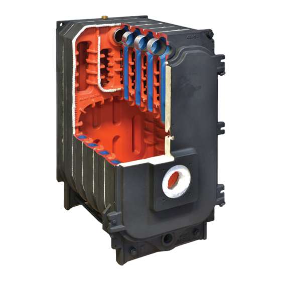
1. General Information The St. Roch Optimajor series boilers are wet base design, sectional, cast-iron boilers for forced hot water heating systems. The Optimajor boilers are designed for firing with oil and deliver high efficiencies through unique design and construction. The Optimajor series boilers are shipped from the factory in assembled blocks and each boiler can range from 6 to 14 sections. -
Page 7: Boiler Block Assembly & Explosion
www.saintroch.us 2. Boiler Block Assembly All OPTIMAJOR series boilers are shipped from the factory in assembled boiler blocks. If, however, the block needs to be split into sections for ease of delivery, please read the following: To assemble split blocks, move sections into parallel and facing each other. Sections may be slid along boards placed underneath the sections. -
Page 8: Boiler Location
3. Boiler Location The following are the minimum clearances to construction or combustible materials: 9” TOP 1. 9” from the top, sides, and rear of the boiler. 2. 18” from the flue pipe in any direction. 24” 3. 24” from the front of the boiler. FRONT 9”... -
Page 9: Installation Of Boiler Trim Kit Components
www.saintroch.us 4. Installation of Boiler Trim Components Trim Kit Components: 1 – Tridicator pressure/temp gauge 1 – ¾” X 3” Nipple 1 – 30 PSI pressure relief valve 1 – ¾” Boiler drain 1 – Cera-fiber Pad for bottom of the combustion chamber 1 –... - Page 10 4. Installation of Boiler Trim Components (Continued..) All piping must conform to state and local codes. The supply and return for Optimajor boilers 2” NPT. Be sure to provide unions and isolation valves at the manifold inlet and outlet of the boiler, so the boiler may be readily isolated for service.
-
Page 11: Piping Of The Boiler
www.saintroch.us 5. Piping The Boiler All piping must conform to state and local codes. Page 11 shows the location and size of the boiler tappings. It is recommended to install unions and gate valves at the inlet and outlet of the boiler, so it may be readily isolated for service. For Canadian installations, a low water cut off is required if the boiler is installed above the level of radiation. -
Page 12: Intake Venting
6. Intake Venting 1. Be certain adequate air is available for combustion and ventilation. a.) Boiler located in unconfined space: Installation in large areas, such as basements, can usually be assumed to provide sufficient air. b.) Boiler located in confined space : (See Figure A. on page 14) If all air for combustion and ventilation is to come from within the building: Two (2) openings shall be provided with one (1) opening commencing within 12 inches of the ceiling and one (1) opening commencing within 12 inches of the floor of... - Page 13 www.saintroch.us 6. Intake Venting (Continued...) c.) Boiler located in a room under negative pressure: If the boiler is to be installed within a home where the operation of exhaust fans, attic fans, kitchen ventilation systems, clothes dryers or fireplaces may create severe negative vent pressures causing unsatisfactory combustion and venting, special provisions should be made for additional make-up air to supply the other air requirements.
-
Page 14: Exhaust Venting
7. Exhaust Venting The Optimajor boiler is a high efficiency unit that requires proper venting. The boiler must be vented to the outdoors by means of a tile lined masonry or an approved pre-fabricated chimney of the size and height recommended by the manufacturer or by a listed “power venting”... -
Page 15: Common Exhaust Venting
www.saintroch.us 7.2 Common Exhaust Venting Common Vent Exhaust: If this boiler is replacing one which was part of a common venting system, it is likely that the vent is to large to vent the appliances still attached to it. To prevent this, at the time of removal, the following steps shall be followed with each appliance remaining connected to the common venting system. -
Page 16: Burner Setup
8. Burner Setup Good, reliable operation with a minimum of service, starts with attention to the small details: Please review burner manufacturer manuals for proper install guidelines! Oil: 1. Setting the nozzle position and electrodes to the manufactures specs using the manufacturer's gauges. -
Page 17: Gas Burner Setup
www.saintroch.us 8.2 Gas Burner Setup This page is only for boilers using a gas burner. If an oil burner is being used, please refer to page 16 for the proper setup of the burner. BURNER MANUFACTURER: RIELLO Boiler Model: OPTI GLP 6 OPTI GLP 8 OPTI GLP OPTI GLP... -
Page 18: Gas Line Piping
9. Gas Line Piping Gas supply piping is to be sized and installed properly in order to provide a supply of gas sufficient to meet the maximum demand without undue loss of pressure between the meter and the boiler. Consult with the National Fuel Gas Code ANSI Z223.1 for proper sizing of gas piping for various lengths and diameters. -
Page 19: Boiler Jacket Assembly
www.saintroch.us 10. Boiler Jacket Assembly NOTE: All piping, boiler controls, gauges and valves must be installed before the jacket has been assembled on the boiler. Refer to the following page to clarify these boiler jacket assembly instructions. Boiler Jacket Assembly: Top Casing Rail (R) Lower Bracket Rear Upper Plate (Rear) - Page 20 10. Boiler Casing Continued STEP 1 Install top and bottom brackets on fron and back tie-rods as shown below. ** MAKE SURE SHELF OF BRACKETS FACE IN TOWARDS EACH OTHER ON ALL 4 BRACKETS STEP 2 Wrap boiler block with insulation material and strap it as shown. STEP 3 Install side rails to each top and bottom brackett from front to back.
- Page 21 www.saintroch.us 10. Boiler Casing Continued STEP 4 Install side common panels onto side rails top and bottom as shown. STEP 5 Interlock the common top cover and proceed along with side panels and covers. STEP 6 Secure two rear panels onto back of boiler casing by starting with LOWER piece first and interlocking the top piece into it.
-
Page 22: Baffle Installation 11
11. Baffle Installation To achieve maximum efficiency, baffles have been installed in the second pass of the boiler. One baffle is installed into each of the 2nd passes as shown in Fig. 10.1. For the baffle to fit correctly, the shortest leg of the baffle must be facing down. -
Page 23: Wiring Hydrostat Control 12.1
www.saintroch.us 12.1 Wiring Hydrostat Control Hydrolevel 3250 controller Low Water Cutoff QHT has added a ground wire and providing a mechanical connection for grounding the Hydrolevel Immersion well back to the 3250 grounding lug. NOTE: All wiring must be done in accordance with applicable state, local and national codes. Use only copper conductors. - Page 24 12.2 Oil Burner Wiring NOTE: All wiring must be done in accordance with applicable state, local and national codes. Use only copper conductors.
- Page 25 www.saintroch.us 12.3 Gas Burner Wiring NOTE: All wiring must be done in accordance with applicable state, local and national codes. Use only copper conductors.
-
Page 26: Maintenance
13. Commissioning Before a gas boiler may be put into operation and tested, it’s gas connection must be leak tested. After installation of oil/gas-fired boiler, operation and performance tests shall be conducted to make certain that the burner is operating in an acceptable manner and that all safety controls and devices function properly. -
Page 27: Warranty
Cast-Iron Water Boilers FIRST YEAR through TENTH YEAR-WARRANTY FOR Optimajor QHT AND Saint Roch WILL NOT BE RESPONSIBLE FOR: SERIES COMMERCIAL HOT WATER BOILERS: QHT warrants Components that are part of the heating system, but that its cast-iron boiler and casing are free from defects... - Page 28 Setting the Standard for Indoor Comfort, Environmental Integrity and Fuel Efficiency QHT supplies the most durable, fuel efficient and environmentally sustainable boilers, radiators and convectors available. From its Portsmouth, NH warehouse facility, QHT assembles and distributes an extensive range of steel panel radiators, towel bars, boilers and fan convectors.
Need help?
Do you have a question about the Optimajor OPTI GLP 6 and is the answer not in the manual?
Questions and answers