Table of Contents
Advertisement
Quick Links
KEEP THIS MANUAL WITH THE BED AT ALL TIMES!
TM
Operation Manual
Impulse Drive System
STOP!
For In-service training or service call your dealer
WARNING -
All persons operating this drive must read
and understand this entire manual before using the drive!
PN 63211
Revised 122012
Patent No. 7,472,438
TF2IDOM1212pn63211.indd
Advertisement
Table of Contents

Related Manuals for Burke Tri-Flex


Summary of Contents for Burke Tri-Flex
- Page 1 KEEP THIS MANUAL WITH THE BED AT ALL TIMES! Operation Manual Impulse Drive System STOP! For In-service training or service call your dealer WARNING - All persons operating this drive must read and understand this entire manual before using the drive! PN 63211 Revised 122012 Patent No.
-
Page 2: Table Of Contents
BURKE, INC. Tri-Flex is a trademark of Burke, Inc. The information in this manual is subject to change without notice. Burke, Inc. makes no commitment to update or keep current, the information con- tained in this manual. -
Page 3: Introduction
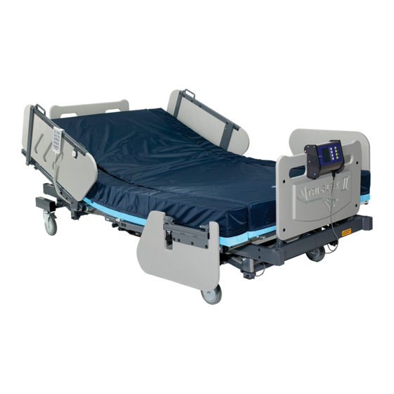
This patient weight usually includes anyone over 400 lbs. (181 Kg.) but not to exceed 1000 lbs. (454 Kg.). The Tri-Flex system can also facilitate patient transport. The impulse drive system allows for safe and easy control during transport. NOTE: This manual covers the use and functions of the impulse drive system. -
Page 4: Symbols And Warnings
Introduction Symbols and Warnings • The symbol below highlights a WARNING: or CAUTION: - A WARNING identifies situations or actions that may affect patient or user safety. Disregard- ing a warning could result in patient or user injury. - A CAUTION points out special procedures or precautions that personnel must follow to avoid equipment damage. -
Page 5: Specifications
Current: 1.0 Amps Charger Output voltage: 24 VDC / 1.5Amps Classification: Class B 1P-54 Manufactured by Burke, Inc. 1800 Merriam Lane Kansas City, Kansas 66106 ® *IMPORTANT: To maximize life and performance you must use batteries with the words “FAA Approved” or “DOT Approved” or “IATA Approved” or “NON-SPILLABLE” printed on the battery label. CE marked is also advised. Such batteries have been tested for leakage, vibration, and case cracking resistance and they have met the specified criteria. These batteries are safe to be... -
Page 6: Identification Of Major Components
Major Component Identification The Impluse Drive System is controlled by a Dynamic Mobility Shark drive controller. This system com- prises of two modules: the power module which is located beneath the bed near the drive wheels, and the joystick/controller which is mounted on the headboard of the bed. Become familiar with all controls with the power button in the OFF position. A detailed explanation follows. Joystick Operation Controls for the Impulse Drive System are located on the Shark Joystick/Controller, which is mounted on the headboard. - Page 7 Joystick Operation Each of the speedometer's 6 large LEDs typically represent 0%, 20%, 40%, 60%, 80% Top Speed 3 Top Speed 2 and 100% of the chair's absolute maximum top speed. Top Speed 4 REMD supports 2 modes of top speed Top Speed 1 adjustment - "5 Speed" and "VSP" modes. In the "5 Speed" mode pressing the 100% Increase Speed and Decrease Speed buttons ...
- Page 8 Joystick Operation 3. BATTERY INDICATOR. The SHARK Information Gauge (located on the joystick console) is the primary source of user feedback. It displays every possible status that SHARK may have. True state-of-battery-charge, including notification of when the battery desperately requires charging. • Any green LED's lit indicates well-charged batteries. • If only amber and red LED's are lit, the batteries are moderately charged. Recharge before undertaking a long trip. • If only red LED's are lit the batteries are running out of charge. Recharge as soon as possible. 4. THROTTLE CONTROL JOYSTICK LEVER. The joystick mounted on the top of the control panel is both the throttle and direction control lever (Push Slowly). Pushing the joystick with your thumb in the direction of the horn button on the control faceplate will make the bed go forward or backward accordingly.
- Page 9 Joystick Operation This means... Notes DESCRIPTION DISPLAY All LED’s OFF Power is OFF or may be locked All LED’s ON Power is ON Less LED’s imply a Steady reduced battery charge Left RED LED is Battery charge is The betteries should flashing be charged as soon as possible...
-
Page 10: Important Safety Information
NOTE: The battery charger provided is specially designed for use with Burke brand equipment. In the unlikely event of failure it should be replaced only with a Burke approved charger to assure proper performance of the charger and Drive System. - Page 11 Important Safety Information Grounding and AC Power Connection: The charger must be plugged into a hospital grade electrical outlet. The unit is provided with an electrical cord which contains a conductor for grounding. CAUTION: - Use appropriate cord/plug provided with this equipment. If it does not fit the outlet, have a properly grounded outlet installed by a qualified electrician. Check all cords for fraying, cuts or damage and replace immediately. Status light on the charger.
- Page 12 Important Safety Information Important Safety Instructions: Because you will be connecting and disconnecting AC voltage to the bed, DO NOT do so in the presence of moisture. Observe caution and safety warnings. a.) Basic Battery Safety i. never smoke or allow open flame around a charging battery ii. never charge a frozen battery iii. use charger for charging gel or AGM batteries only; This charger is recommended for use with deep cycle-type batteries.
-
Page 13: Basic Operational Instructions
Operational Instruction METHODS FOR CONTROLLING THE DIRECTION OF THE TRI-FLEx II WITH THE IMPULSE DRIVE SySTEM Pushing the Control Moving the knob directly to Knob straight forward the left (while stationary or will cause the bed to moving) will cause the bed to move in a forward di- turn to the left. Conversely, rection. -
Page 14: Your First Drive
Operational Instruction For your first drive, we recommend the following. When possible, always work with your dealer to learn how to use your bed. If you have any questions concerning the drive or bed please call your dealer. 1. Make sure the area is a flat, hard, smooth, open and free of obstacles. 2. Make sure the bed is in it’s lowest hi-lo position and all the casters are unlocked. All the casters must be unlocked for the drive to function properly. -
Page 15: Braking System
Operational Instruction The Impulse Drive System Braking Systems The drive system’s brake systems allow for smooth start up and safe braking without undue jerking. There are three (3) separate modes to the braking system: Regenerative, Dynamic, and Posi-Lock Electric Braking. All braking occurs automatically during the drive operation. Each type of braking is described in the following. 1. Regenerative Braking is activated while driving the bed down an incline. When the bed picks up speed going down the incline, the motor generates electricity. -
Page 16: Transporting Bed/Patient
5 degree incline with a patient. Extra care should be taken when transitioning at the bottom and top of ramps. Loss of traction at the drive wheels may cause damage to the bed and injury to persons. NOTE: Remember to plug the Tri-Flex bed into the wall outlet once transport of the bed is complete. IMPULSE DRIVE - OPERATION MANUAL... -
Page 17: Weight Indicator (W.i.) System
Operational Instruction Weight Indicator or W.I. (if applicable) If your bed is equipped with a (W. I.), there will be some extra steps to be aware of to insure the (W. I.) functions properly. The load cells for the (W. I.) are mounted above each of the four casters. Thus the full weight of the bed and patient must be transferred through the casters. -
Page 18: Cleaning / Disinfection Instructions
Routine cleaning is to be done on a daily basis by wiping the surfaces with a disposable cloth using warm water and a mild detergent or cleaning solution In the event of known infection, blood or body fluids contamination, clean first, then disinfect follow- ing facility guidelines using disinfectants at their recommended concentrations. Burke recommends a chlorine based solution no greater than 10,000 PPM for routine decontamination. The bed and components should also be cleaned and disinfected between patients and before returning to service after a period of storage, per facility guidelines. -
Page 19: Storage Of The Bed
FOLDING THE BED FOR TRANSPORT OR STORAGE The bed with the drive system will fold and roll around on the transport casters just like a Tri-Flex bed without a drive system. The drive system cannot be used when the bed is folded. -
Page 20: Service/ Fuses
Cleaning, Disinfection, Storage and Service CHANGING THE BATTERIES The drive system batteries are located in the metal enclosure underneath the foot end of the bed. 1. Remove 4 screws on top of the battery box and set battery box lid aside. 2. Remove the 4 bolts connecting cables to the battery posts using a 7/16” / 11 mm wrench. Take care to avoid dropping the hardware into the box. Remove the battery hold-down bar. 3. Lift the batteries from the box. Avoid damage to the cables or the circuit breaker. -
Page 21: Maintenance / Inspection Check-List
Refer to the service chart provided in this manual for basic problem solutions. Major service of this equipment should be referred to qualified personnel. Refer to circuit layout diagram and part identification diagram provided in this manual. The manufac- turer of this equipment will provide assistance to the user’s appropriately qualified technical personnel to repair those parts of the equipment which are designated by the manufacturer( Burke) as repairable. Use only replacement components which are approved and designated as acceptable by the manufac- turer ( Burke) See also the options/mattress manuals for specific service instructions for the Impulse Drive, Low Air Loss Mattress and Barri-Float Foam Mattress. -
Page 22: Troubleshooting
Troubleshooting DIAGNOSTICS Note: SHARK IS NOT USER SERVICEABLE. Specialized tools are necessary for the repair of any SHARK component. INTRODUCTION A flashing SHARK information gauge indicates there is an abnormal condition somewhere on the drive system. The components that SHARK provides fault information for include the motors, the park brakes, the batteries, the cabling and the SHARK modules themselves. -
Page 23: Frequently Asked Questions
2. Circuit breaker on breaker box. An “Open” circuit breaker indicates some type of drive system overload. Consult with your dealer to determine the problem. 3. Excessive weight on the bed. Remember that the Tri-Flex II takes a maximum of a 1000 lbs. (454 kg.) patient. - Page 24 NOTE: All foams and fabrics will loose resiliency with use. This is considered normal wear and is not covered by this warranty. Burke’s liability under this warranty and the buyers exclusive remedy is limited to the cost of materials to repair the defective parts or the replacement and should not exceed the original purchase price.
Need help?
Do you have a question about the Tri-Flex and is the answer not in the manual?
Questions and answers