
Related Manuals for Spid Elektronik MD-01

Summary of Contents for Spid Elektronik MD-01
- Page 1 SPID Elektronik User manual for controllers MD-01 / MD-02 / MD-03 for firmware from version 2.0 27th October 2022...
-
Page 2: Table Of Contents
Table of Contents Table of Contents ............................2 General ............................... 5 Block diagram ............................. 5 Controller technical data ..........................6 Panels descriptions ............................. 6 Front ............................... 6 Back ................................ 6 How to connect the controller to the BIG-RAS/HR rotor: ................7 #1 Connection of Azimuth &... - Page 3 KIND ..............................20 INPUT ..............................20 GEAR ..............................21 MIN ANGLE ............................22 MAX ANGLE ............................22 MAX POWER ............................. 22 PULS TIMEOUT..........................23 Setting RS232 port (SET COM0, SET COM1) ..................23 STATE ..............................23 BAUD..............................23 DATA BITS ............................23 STOP BITS ............................
- Page 4 Configuration ............................41 CCM - CURRENT CONTROL MODULE ......................42 Installation of the CCM module in the MD-01 ..................42 Installation of the CCM module in the MD-02 ..................44 Installation of the CCM module in the MD-03 ..................47 Configuration of CCM module ......................
-
Page 5: General
General MD-01 / MD-02 / MD-03 units are electronic rotor controllers. They are multifunction devices allowing various combinations of work settings. Single rotors (e.g. two Azimuth rotors), double rotors (one Azimuth / Elevation rotor or one X/Y rotor) can be connected to the controller. The system provides work with DC motors. -
Page 6: Controller Technical Data
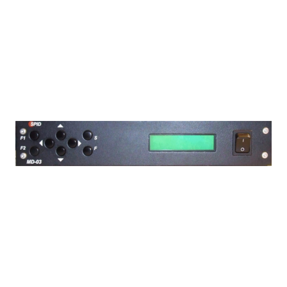
1 USB host port – not active 1 USB device port – visible in the system as a virtual COM port 1 RJ45 Ethernet port Panels descriptions Front MD-01 MD-02 MD-03 1. Keyboard. 2. LCD screen. 3. On/off switch. Back... -
Page 7: How To Connect The Controller To The Big-Ras/Hr Rotor
MD-02 MD-03 1. Input socket for Connecting Ground (rest of NC pins). 2. Power input for Rotor motors (fuse 40A). 3. Socket for connecting modules such as CAN, RS485, RS422 or analog inputs. 4. Pulse input for systems with two HALL sensors. 5. - Page 8 The rotor is connected to the controller via the supplied plugs (4-Pin), they are used in to power the Azimuth and Elevation motors. In the controllers in the AZ and EL outputs, pins 1 and 2 are always used to power the motors. Remember to verify the correctness of connecting the polarity of the motor power supply.
-
Page 9: Sensors Connection
Sensors connection #2 Connection of the sensor cable from the rotator to the controller (AZ/EL) The connection from the rotor side is carried out by an eight-pin connector type MIC328, which is located in a PVC box at the rotator, on the back side of the controller there is a nine-pin connector of type DB9. A shielded six-wire cable should be used for connection. -
Page 10: Operating
Operating The controller can be operated using the keyboard located at the front panel or a computer with the appropriate software installed (e.g. PstRotator). Modes: NORMAL – standard operating mode MOTOR ANGLES – calibration mode of the actual rotator’s position relative to geographical directions, ... -
Page 11: Motor Angles
YAESU, which in the settings can be assigned to the selected communication port (COM0, COM1, USB D and ETH). Keyboard function: The [Right] and [Left] buttons are used to rotate the antenna in the azimuth plane: o direction Right - the antenna rotates clockwise, the value of the angle on the display increases, o direction Left –... -
Page 12: Speed Calibr
Verification of the actual position of the antenna in relation to the displayed values should also be done preventively. This is to maintain the operation of the antenna and wiring within the assumed angular limits. It is suggested that during the operation of the rotor, observe its operation and the position of the antenna (directly or through the camera) and in the event of irregularities, immediately stop the rotor by switching off the controller. - Page 13 The next step in optimizing the work is to set the ramps of start power gains (START POWER) and stop power (STOP POWER) of the voltage supplying the motors and periods (START TIME and STOP TIME respectively): 1. Usually, in the case of even complex antenna systems, it is sufficient to set a single-threshold start and stop ramp.
- Page 14 3. Explanation of the operation of ramps on the example of the following graphs: A diagram (above) of the starting ramp, where the controller will start the motors with a power of START POWER of 20% (in this case such as MIN POWER) and at the time of START TIME 1 (here 2s) will smoothly increase the power to the value of MAX POWER (in this case to 100%).
-
Page 15: Controller Configuration
A diagram of the stop ramp, where the controller will start the stopping process from MAX POWER (in this case 100%) to STOP POWER (in this case 20%), and this process will take place during STOP TIME 1 (here 3s). Comment: if you select the START POWER and/or STOP POWER value smaller than MIN POWER, the controller will use the MIN POWER value in these places, similarly for the START POWER and/or STOP POWER value greater than MAX POWER, the controller will use the MAX POWER value in these places,... -
Page 16: Motor Configuration
modules - the [Right] and [Left] buttons, and the parameter value changes with the [Up] and [Down] buttons. Module selection is done by pressing the [S] button. The [F] button is used to exit the configuration. After pressing, a question appears about saving any changes in the configuration. - Page 17 View of the X/Y rotor with axis marking, motors names and operating ranges The correct positioning of the X/Y rotor should be done with setting the "zero" initial position of the rotor on the mast: the positions of the X and Y gears should be set in the middle of the operating range (90 deg.), which should lead to the position of the mounting plane of the antenna mounting plate horizontally in both planes (as shown above).
-
Page 18: Start
o Y(180⁰) = 180⁰ AZ To set the mounting position of the rotor operating in 1:AX, 2:EY template and to calibrate the indication, switch to 1:XX, 2:YY template. Do not forget to back to the 1:AX, 2:EY template when setup is done or leave 1:XX, 2:YY template just when going to send raw X-Y data to the controller (Non-standard setup, only for specific application!). -
Page 19: External Control (Control Xx)
Properties: o optimized to track satellites in LEO orbit, o increases smooth operation and reduces the load on motors, gears and relays (note: at the expense of a slight reduction in accuracy), o works only with sensors type HR and CAN Bus. ... -
Page 20: Protocol (Prot. Xx)
Protocol (PROT. xx) Choosing communication protocol between the controller and the control device (e.g. a computer with the appropriate program): SPID ROT1 SPID ROT2 YAESU Motors setting (SET MOTOR 1, SET MOTOR 2) STATE Read-only parameter. It depends on the choice of template (TEMPLATE) in the configuration of motors. -
Page 21: Gear
2. Then turn off the power of the controller and connect ONLY ONE selected to configure the encoder. 3. In the next move (with the controller constantly turned off), when holding the F2 key, turn on the power of the controller and the device starts in Setup CAN M1 mode. 4. -
Page 22: Min Angle
It should be noted that from firmware v2.0 the designation of the rotor gear has changed. During the process of replacing the software with a newer one, the controller itself converts the old values into the correct, new ones and usually no user intervention is required in this regard, however, the gear ratios are key parameters and their correctness should be verified by the user. -
Page 23: Puls Timeout
PULS TIMEOUT Specifies the time after turning off the motor, if there are no pulses from the motion sensor. Applies only to rotors with DIGITAL sensors. Setting RS232 port (SET COM0, SET COM1) STATE The parameter is read-only. Values ON – on, OFF – off. BAUD Baudrate: 600, 1200, 2400, 4800, 9600, 19200, 38400, 57600, 115200, 230400 and 460800. -
Page 24: Setting Ethernet Port (Set Ethernet)
Setting ETHERNET port (SET ETHERNET) The Ethernet port is set to obtain a dynamic IP address. Communication with this port is done using one of the protocols (SPID ROT1, SPID ROT2, and YAESU). For example, the controller obtained an IP address from the DHCP server 192.168.0.10. -
Page 25: Dimensions
Dimensions: MD-01 FRONT MD-01 BACK... - Page 26 MD-02 FRONT MD-02 BACK...
- Page 27 MD-03 FRONT MD-03 BACK...
-
Page 28: Accessory
ACCESSORY HR sensors module: CAN BUS sensors module:... -
Page 29: Cable Connections
CABLE 8 x 0.5 mm2 BLUE “-“ Look BOX sheet 1 -- 3 -- power + 12-30VDC motor 2 -- 4 -- ground Rotor RAS/HR BIG-RAS/HR CABLES 2 x 1,5 mm2 MD-01 MD-01 controller to RAS/HR or BIG RAS/HR connection diagram... - Page 30 RED +15 VDC (Imax – 2A) controller power power + 12-30VDC elektronica ground BLUE “-“ IN - IMP RED +14-18 VDC (Imax – 20A), BigRAS/HR and SDD +24-30 VDC (Imax – 12A) rotator power BLUE “-“ 1 -- 3 -- power + 12-30VDC motor 2 -- 4 --...
- Page 31 BLUE YELLOW BROWN BLACK ORANGE GREY GREEN Distance 100 - 150 m what 3 cable IMP2 EL cable 1 + Ground IMP1 EL IMP1 AZ cable 2 + Ground IMP2 AZ PLUS ( + ) cable 3 + Ground MINUS ( - ) Distance 0 -100 m what 1 cable...
- Page 32 + 12-30VDC motor schemat dla AZ , AZ 2 -- ground Kabel do podlaczenia CABLE 6 x 0.5 mm2 Rotor 2 x RAK 2 x RAU CABLES 2 x 1,5 mm2 MD-01 Connection between RAK/HR or RAU/HR rotator and MD-01 controller...
- Page 33 Sensors connection at rotator HR type Sensors connection at MD-01 controller BROWN GREEN BROWN GREEN PINK GREY Shield grounded with minus „-„ on power supply of a sensor BLUE YELLOW BROWN ORANGE BLACK DB9 MALE Distance 0 -100 m what...
- Page 34 Connection between SPX HR rotator and a controller...
-
Page 35: Ethernet Module V1
ETHERNET MODULE v1 User installation Unscrew the screws that fix the top cover of the controller. Open the controller by removing the cover and find the empty space on the left when the display is turned facing the user. Place the Ethernet module on the connector and secure it with screws. -
Page 36: Configuration
Configuration The operation mode of the module is configured by micro-switches:... -
Page 37: Ethernet Module V2
ETHERNET MODULE v2 User installation The complete Ethernet module set includes: main unit, mount board and connection cable. Ethernet module set (from left to right): main unit, mount board, connection cable Unscrew the screws that fix the top cover of the controller. Open the controller by removing the cover and find the empty space on the left when the display is turned facing the user. - Page 38 Main board connector Put 2x7 pin connector of ready for mount board mount board to the main installation board connector Mount board installed...
- Page 39 Put Ethernet main unit to the mount board by gently pulling side corner of PCB above Align pins of the main unit and the mount board inline...
- Page 40 Carefully plug connection cable’s asymmetrical connector to connect both main and connection units Plug connection cable’s other side connector to the connection unit and screw gently top mount bar Put on and screw the cover.
-
Page 41: Configuration
Configuration The Ethernet module is configured by controller’s menu. After connecting the LAN cable between computer and controller the IP address is assigned via DHCP. To check assigned IP address go to the SET ETHERNET menu and press arrow right to start checking process: After a while proper address appear (example here): To communicate with controller via LAN cable user must choose ETH mode at MOTOR CONFIGURATION menu. -
Page 42: Ccm - Current Control Module
CCM - CURRENT CONTROL MODULE Installation of the CCM module in the MD-01 A complete set CCM module... - Page 43 Unscrew the screws that fix the top cover of the controller. Remove the cover. Unplug and remove original cable Connect new cable Then follow installation steps of MD-02 CCM module (below). Secure the stable position of the CCM module to prevent any contact or short circuit with the components and the controller housing.
-
Page 44: Installation Of The Ccm Module In The Md-02
Installation of the CCM module in the MD-02 Unscrew the screws that fix the top cover of the controller. Remove the cover. CCM module Unplug black cables form mainboard... - Page 45 Connect black cables to free connectors of CCM module Connect corresponding wires of CCM module to free connectors of mainboard...
- Page 46 Connect harness between the CCM and the HR module Secure the stable position of the CCM module to prevent any contact or short circuit with the components and the controller housing. Put on and screw the cover.
-
Page 47: Installation Of The Ccm Module In The Md-03
Installation of the CCM module in the MD-03 Unscrew the screws that fix the top cover of the controller. Remove the cover. A complete set CCM module... - Page 48 Unplug black cables form mainboard Connect black cables to free connectors of Connect CCM module corresponding wires of CCM module to free connectors of mainboard...
- Page 49 Unplug and remove original cable Connect new cable New CCM’s cable plugged (controller without HR module) Connect cable between the CCM and the HR module New CCM’s cable plugged (controller without HR module) Secure the stable position of the CCM module to prevent any contact or short circuit with the components and the controller housing.
-
Page 50: Configuration Of Ccm Module
Configuration of CCM module 1. Choose SET MOTOR 1 at the controller menu. 2. Turn on CCM module by setting CURRENT LIMITER to ON. 3. Choose value of module’s sensor C. SENSOR according to installed CCM module. 4. Set MAX CURRENT value to the maximum motor supply current at which the protection will activate. Set MAX O/C TIME as the time after which the protection will activate. -
Page 51: Operating Ccm Module
Operating CCM module During the operation of the controller, the CCM module controls the current levels of the motors. It happens in the background. In case of exceeding the declared values of the maximum current MAX CURRENT and/or the MAX O/C TIME, the controller, depending on which engine is exceeded, will turn off the power supply in an emergency for about 10 seconds with the following message: After 10 seconds of emergency power off, the controller is ready to work automatically.
Need help?
Do you have a question about the MD-01 and is the answer not in the manual?
Questions and answers