Table of Contents
Advertisement
Quick Links
Advertisement
Table of Contents

Related Manuals for Spid Elektronik MD-01

Summary of Contents for Spid Elektronik MD-01
- Page 1 SPID Elektronik Driver MD-01 MD-01...
-
Page 2: Table Of Contents
Front ............................... 5 Back ................................ 5 Operation..............................8 Normal mode (NORMAL) ........................8 Calibration mode (MOTOR ANGLES) ...................... 9 Driver MD-01 configuration ........................9 Motor configuration ..........................9 TEMPLATE ............................9 Start ..............................10 Stop ..............................10 External control (CONTROL xx) ......................10 Protocol (PROT. - Page 3 START POWER, START TIME ......................12 STOP POWER, STOP TIME ......................... 13 STOP AT ............................13 PULS TIMEOUT..........................13 SET COM 0, SET COM 1 ......................... 13 STATE ..............................13 BAUD..............................13 DATA BITS ............................14 STOP BITS ............................14 PARITY ...............................
-
Page 4: Introduction
Introduction MD-01 is an electronic driver used for turning rotors. It is a multifunctional device, allowing for various combinations of work setting. The driver may be connected to two single rotors (e.g. two Azimuth rotors) or double (one Azimuth / Elevation rotor). The basic circuit provides operation with direct current motors. -
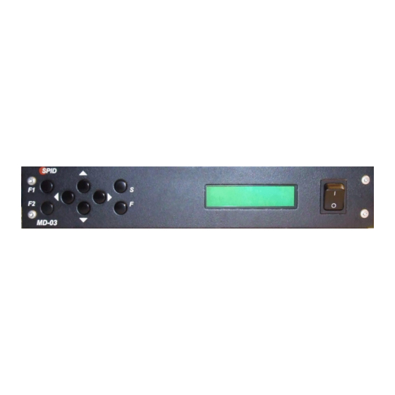
Page 5: Photos And Description
Photos and description Front 1. Keyboard. 2. 2x20 characters display. 3. Switch-key. Back 1. Plug-in socket to turn on Ground (the remaining NC PINs). 2. Rotor motor supply input (FUZE 40A). 3. NC, in the future planned for connecting modules, e.g. CAN, RS485, RS422 or analogue inputs. 4. - Page 6 The rotor is connected by using the delivered connectors (4-pin type) and are used to drive the Azimuth and Elevation engines. AZ & EL (drawing below) are market at the back site of the MD-01 controller Both AZ &EL are using pin 1 and 2 from both connector.
- Page 7 MIC328 is at the rotor, DB9 Male is at the MD-01 controller back site...
-
Page 8: Operation
Operation MD-01 Driver may be operated with the use of a keyboard or a computer. MD-01 module has two modes (MODE). NORMAL – normal mode. MOTOR ANGLES – calibration mode. To change the mode, use the [F] key. -
Page 9: Calibration Mode (Motor Angles)
[F] button. Driver MD-01 configuration When driver MD-01 is in NORMAL mode you can use button [S] to enter configuration. The structure of driver configuration is modular. Select module using buttons [Left] or [Right]. When you select module you can use button [S] to enter in its parameters. Moving between parameters is done with buttons [Left] or [Right]. -
Page 10: Start
1:AZ, 2:AZ - there are two motors connected to the controller, which is rotated in azimuth only. Start Motors run mode: MAX SPEED - motor starts with max speed, that is set for each motor separately in modules SET MOTOR 1 and SET MOTOR 2, described later, ... -
Page 11: Protocol (Prot. Xx)
SPID MD01 - in the future. New communication protocol from SPID Elektronik YAESU - in the future. BRITE - in the future. New protocol created by SPID Elektronik firm and Space Analysis Center in Warsaw. HyGain - in the future. -
Page 12: Max Power
MAX POWER Maximum power in a percent’s of full power, which the driver can provide rotor. START POWER, START TIME We use if we want to obtain a so-called soft-start. We can set one, two or three-stage motor start (START POWER 1, POWER START 2, START and START POWER 3 TIME 1, TIME 2 START, START TIME 3). Power (START POWER) is introduced as a percentage of full power, which can provide a driver for the rotor. -
Page 13: Stop Power, Stop Time
Example 2: three-step - set the POWER START 1 = 20% START POWER 2 = 30%, START POWER 3 = 50%, START TIME 1 = 3s, START TIME 2 = 3s, START TIME 3 = 3s, MAX POWER = 100%. This means that the rotor starts with 20% power, within 3 s power reaches 30%, followed by 3s power reaches 50% and last 3 s power up to 100%. -
Page 14: Data Bits
The Ethernet port is set to dynamic IP address. Communication with this port is done with the help of one of the protocols (MD01 SPID, SPID ROT1, SPID ROT2, Yaesu, or HiGain BRITE). For example, the MD-01 driver received the IP address from a DHCP server 192.168.0.10. It can connect to it, for example, Hyper Terminal by selecting the type of connection TCP / IP (Winsock), set host address 192.168.0.10 and port... - Page 15 Controller Dimensions: Controller MD-01 Dimensions FRONT Controller MD-01 Dimensions BACK...
Need help?
Do you have a question about the MD-01 and is the answer not in the manual?
Questions and answers