Table of Contents
Advertisement
Quick Links
Advertisement
Table of Contents

Summary of Contents for Getinge GEV TS 121650 AR-2
- Page 1 GEV TS 121650 AR-2 PFIZER ROBOTIC SYSTEMS 0011393179-010 USER MANUAL...
-
Page 2: Table Of Contents
TABLE OF CONTENTS PREFACE ..............................5 INTRODUCTION ............................6 SAFETY ..............................7 Attention symbols ..........................7 Warnings ............................7 Advice .............................. 7 Symbols on the unit ......................... 8 Electrical hazards ..........................8 Other hazards ..........................8 Machine Identification ........................9 General ............................ - Page 3 General functions .......................... 22 Sluicing of empty racks ......................... 22 Emptying of system ........................22 Hold time monitoring........................22 Separation of autoclave cycles ....................... 23 Request access, Haake locks on gates ................... 24 Haake boxes ........................... 24 Entering the facility area ........................ 25 Exit area ............................
- Page 4 Manual/Auto mode ........................49 Starting program execution ......................50 Manual operation of robot. (Jog window or Quick selection) ............51 Home position..........................53 Picture illustrates robot in home position ..................53 Move the robot to home position ....................55 Gripper ............................57 Open/close manually........................
-
Page 5: Preface
PREFACE This USER MANUAL, contains all the information you need in order to safely operate your Evomatic AB equipment. Please read and follow the entire manual carefully, and please pay special attention to the framed warnings and caution remarks. See “Attention symbols”... -
Page 6: Introduction
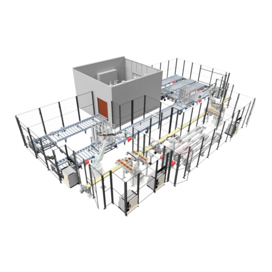
INTRODUCTION This system is designed to receive tubs with syringe nests, load and unload a sterilizer. Put back the syringe nest in its tub and proceed down the line to inspection and packing. Depending on process, the system also store empty tubs in a separate buffer zone until the last sterilized nest comes to unloading side at the end of a batch from filling line. -
Page 7: Safety
SAFETY Attention symbols Some of the warnings, instructions and advice in this manual are so important that we use the following special symbols to draw attention to them. The designs and symbols used are: Warnings This symbol indicates a warning in the manual. It’s a warning of a hazard that may lead to more or less severe injury and in certain cases mortal danger. -
Page 8: Symbols On The Unit
Symbols on the unit Electrical hazards This symbol is a warning for electrical hazards. Other hazards This warning symbol alerts the user to other hazards that may occur. -
Page 9: Machine Identification
Machine Identification The Robotic system Type Plate The unique identification information for the Robotic system is found on the Robotic system type plate, attached to the machine. When contacting Evomatic concerning the Robotic system, information included in the type plate is required. The CE mark ensures that the Robotic system complies with all relevant European directives of the European Economic Area (EEA) / the European Economic Community (EEC). -
Page 10: General
General All machines can be dangerous in case of improper operation. It is therefore of the utmost importance that all users of the machine read through, understand and observe the following security measures and warnings. Read through the instruction regularly. All safety precautions have been taken as far as possible when designing the machine. - Page 11 Equipment in raised position, moving parts. Equipment in the raised position, shall be blocked or otherwise adequately secured in its raised position before intervention/maintenance. In this raised position, application racks drop down 40mm when air pressure disappears. Depressurizing takes place when zone is unlocked.
-
Page 12: Emergency Stop
Emergency stop Two types of emergency stop circuits are located near the equipment and they have different functions, see Emergency stop for more details. The emergency stop stops all functions and releases pressure in the pneumatic parts of the equipment in cases where pneumatic movements are a risk. Central reset of the safety circuit (emergency stop) is a requirement for restart, see Restart after an emergency stop. -
Page 13: Emergency Stop Placement
Emergency stop placement The map below shows the placement of the emergency stop devices for the sterilizer and the robot zone with its robots. There are two kinds of emergency stop labels are used depending on the purpose of emergency stop. The T42205a are used for the sterilizer and the T42205b are used for the robot cells. -
Page 14: Protection Zones
Protection zones The machine is divided into different protection zones (which are also operating zones). When the gate and light protection is turned off in the zone, pneumatics and electricity are turned off to the equipment where it is considered that movements pose a risk. One exception, as mentioned above, is the of pneumatics to robotic gripper. -
Page 15: Working Methods In Case Of Problems Or Breakdown
Zon3 Gate 2 3F7SG2 Haake key back in Gate used for access robot cell original place Light barrier 100SG1 Outside, other zone Protection between Zone 1 and 2. Only active when 1 of the zones is 1A2S2, 2AS2 turned off Zones Zone Description... -
Page 16: Restrictions
Restrictions Risk area and personnel requirements. The production cell is surrounded by protective fences and monitored gates. Protection zones Access to the cell is described in section Repair and replacement of spare parts. During the warranty period, Pfizer must contact Evomatic if anything breaks. If anything is changed, original manufactured parts must be used. -
Page 17: The Process
THE PROCESS General function The facility is divided into 3 zones. They are normally started in Auto together as one zone on HMI. Separate mode selection and start per zone is possible. See Error! Reference source not found. Error! Reference source not found.. Tub, nest, and rack handling Tub, Nest loading 1. - Page 18 1. Search error (Position search outside of limit) 2. Tub stacks are too close to each other in leaving or picking position on the buffering conveyors. For more details about problems and error handling see section ERROR HANDLING Rack handling 1.
-
Page 19: Operation Instructions
OPERATION INSTRUCTIONS General Before start Before start-up, all those working at or adjacent to the installation must have taken part in and understood all the manuals supplied with the installation. Make sure the plant is free from loose and foreign objects. ... -
Page 20: Auto Mode
Auto mode When the zones are in operation mode Auto, all movements are controlled automatically by PLC and robot. When global Auto is selected, all 3 zones go to Auto. It is possible to switch one zone back to Manual or Semi-auto mode. Activate operation mode Auto 1. -
Page 21: Manual Mode
Manual mode If the zone is in operation mode manual, individual movements can be run manually from the operator panel. The movement is started by selecting the desired equipment on the HMI. When global Manual is selected, all 3 zones go to Manual. It is possible to switch one zone back to Auto or Semi-auto. -
Page 22: General Functions
General functions Sluicing of empty racks The autoclave has a function where empty racks can be transported through the autoclave without performing a sterilization cycle (see Functional Specifications autoclave). The transport system logic in automatic mode is as follows: 1. Every empty rack is sluiced until a full rack arrives at the loading position. 2. -
Page 23: Separation Of Autoclave Cycles
Separation of autoclave cycles In order to separate autoclave cycles downstream of the unloading robot, empty tubs are inserted before a new autoclave cycle is unloaded. Whenever a new (different) cycle ID is detected in the unloading station, in comparison with previous unloaded IDs, 3 empty tubs are sent downstream the conveyor prior to unloading the rack in unloading position. -
Page 24: Request Access, Haake Locks On Gates
Request access, Haake locks on gates Haake boxes Every zone 1-3 has an Haake box with A-keys and an unlock button. Each key is labeled with the number for which zone it belongs to, as well as the letter for which function it has. -
Page 25: Entering The Facility Area
Entering the facility area 1. On HMI select “Entrance” to the desired zone 1-3 (Loading, Unloading or Buffer), there is one button for each zone. The button starts to flash when entrance is requested. 2. In Auto wait until the equipment stops in a controlled way, where production is not affected by a stop. -
Page 26: Restart After Stop
Restart after stop Restart after an emergency stop The emergency stop should be reset by the same operator who activated it. The factory's additional safety procedures must be followed. 1. Correct the error that caused the the emergency stop. 2. Ensure that no person can get injured. 3. -
Page 27: Alarms
Alarms In this project Pfizer’s standard is used for alarm categories. Active alarms are displayed on the operator panel. The alarms that need acknowledgement, are acknowledged by pressing the reset alarm button on the HMI. It’s possible look at historical alarms on the HMI. The plant has four alarm groups. A, B, C and D-alarms and each group has classes. -
Page 28: Manual Operations
Manual operations Manual rack handling A rack can at any time be unloaded/loaded on both sides of the system, however, there are restrictions on exactly which racks that can be loaded/unloaded in order to not impede the proper functioning of the robotics system. The picture above shows a flow-chart over the robotic system. -
Page 29: Loading Side - Manual Loading
Loading side – manual loading Rack entered Pop-up/decision Confirm that the rack is not empty Empty racks should be loaded CANCEL RACK at unloading side, remove rack -> NOT ALLOWED -> alarm that triggers a pop-up(2)(C3) Rack ID CONFIRMED - Data stored MANUALLY Timestamp entered: Confirmation &... -
Page 30: Autoclave Cycle, Pharma-Alarm Handling
Autoclave cycle, pharma-alarm handling Supervisor input (dialogue pop-up) FLAG AUTOMATIC UNLOADING PROCEED TO AUTOMATIC AUTHORIZED UNLOADING? Cycle conform TRUE AUTOMATIC FLAG TRUE UNLOADING FALSE Cycle non-conform Cycle non-processed Pharma-alarm (e.g. hold time) FLAG FALSE REPROCESS Test-mode: reprocessing enabled MANUAL Redestination -> UNLOADING autoclave-entrance REPROCESS... -
Page 31: Unloading Robot Logic
Unloading robot logic The unloading robot will make the decision to unload (or not unload) a certain rack based on the following flowchart. Continue to loading side robot EMPTY RACK NOT EMPTY Status: pharma-alarm FALSE Processed conform IF Cycle ID (n)=/= Cycle ID (n-1) ADD Cycle ID (n) to (compare with last one in shift shift register... -
Page 32: Error Handling
ERROR HANDLING Some of the errors might not be covered or handled by the guide below. If this is the case, it is utterly important that everyone who does manual change or troubleshoots the robot system is familiar with the program and know how to manually use the robot system. For more basic robot handling see section Robots, basic functions further down in the manual. - Page 33 None of the sensors are active. Sensors to check: iGripperOpened & iGripperClosed As long as you press 2 or 4, this screen will appear and when you press 5, the program continues (with the gripper in the same status as you left it in).
- Page 34 Mechanical gripper failure If the gripper fails to open or close the following screen appears. If you select 1 – the program continues as expected. If you select 2/3 the gripper will try to open/or close If you press 5 – The robot aborts its current program and moves to home its position Always check the gripper before selecting commands.
- Page 35 Lost product (Nest) during transportation. If a product falls out of the gripper an alarm will notice the operator, please follow the instructions below to perform a reset. Press 1 if the nest is in the gripper. If you press 2 - The robot aborts its ongoing program and moves to its home position. If you for some reason move the program pointer to Main you must also empty the nest stations with already placed nests to prevent collision.
- Page 36 No sleeve detected in rack Robot always check that a sleeve is present in the rack before picking. This to prevent failure if by any reason a sleeve is missing from its position. Check the current position, (in this example pos. 14) and make sure there is a valid sleeve in that position.
-
Page 37: Lost Product (Sleeve) During Transportation
Lost product (Sleeve) during transportation. If a product falls out of the gripper, an alarm will notice the operator. Please follow the instructions below to reset the system. Select 1 if everything looks ok and the sleeve is properly mounted in the gripper. Select 2 to abort the current program. -
Page 38: Zone 1
ZONE 1 In case of production errors in zone 1 follow operations below to solve different situations. Control, No nest in tub Pos.106 If tubs entering the system has a missing a nest or is damaged, an alarm notify the operator. - Page 39 Before the robot begins to pick any tubs, the system will perform a check to assure that the gripper is empty. In the case of tubs in the gripper- please remove the tub manually from the gripper and press OK. If there is no tub present in the gripper, check the sensor and/or cabling and clean the detection area of the sensors.
- Page 40 If the arms-cylinder does not reach its inner or outer position this screen appears. Select option 1 or 2 to move the cylinder in and out. Check the sensor/ cabling. Adjust the sensor/s if needed. Select 1 to continue without action, the program continues as expected. Select 5 to exit ongoing program, the robot will move to its home position.
- Page 41 Please note! You must add exactly the same number of tubs that you removed from the stack, otherwise the system will not be able to function properly. Using the log can help you find errors/faults. For every error created there is an error log which is being saved with additional information.
- Page 42 Tap here first and then select” User” Tap on the log If the specific part is supported, you might find suggestions on what to check or replace.
- Page 43 Press OK to close this message. This robot system, delivered from Evomatic, has a function to prevent the customer/operator from loading the wrong program into the systems controller. The system will refuse to start if there is a mismatch between the program and the controller.
-
Page 44: Control Panel
Control Panel Cabinet The robot line is equipped with a main switch for the cell´s electrical cabinet, this is located on the main cabinet AK1. Name Type Description Main Switch Turn switch Cuts all power to robot handling equipment, including UPS for PLC supply. -
Page 45: Light Tower, Pfizer Standard
Light tower, Pfizer standard Green light indicates that the machine is in operation. Blinking green light indicates that the machine is in waiting mode, automatic restart possible at any time. Blinking orange light indicates a pre-warning. Orange light indicates that the system is in jogging mode, (not used here). Red light indicates that the machine is stopped due to an alarm. -
Page 46: Robots, Basic Functions
Robots, basic functions ABB-menu Programable Status field function buttons ABB-menu Close button Safety switch Quick menu... - Page 47 Menus Hot Edit is used to change positions in any operation mode, even when the program is running. Inputs/Outputs, I/O, are signals used in the robot controller. Jogging functions are located under jogging, the most common functions are also located under quick menu.
- Page 48 Under Backup and Restore you can create backups of the system and also restore the system from previous backups. Please note! A backup should always be created before starting to work/change the system. Calibration is used to calibrate mechanical units on the system Control panel is used to setup various function and settings of the system Shows a summation of events.
-
Page 49: Robot Pendant
Robot pendant Manual/Auto mode Quick menu Key selector Auto/Manual mode... -
Page 50: Starting Program Execution
Confirm with acknowledge first, then Starting program execution From the Production window you can start the robot. Start Step mode Step mode forward Stop backward Start: Robot starting program execution. Step mode forward: Robot performs one instruction at a time, forward. ... -
Page 51: Manual Operation Of Robot. (Jog Window Or Quick Selection)
Manual operation of robot. (Jog window or Quick selection) To Quick select. To Jogging window Choose Choose tool Choose unit Choose work object motion type Actual coordinates Directions of the joystick... - Page 52 Motion mode Quick select Increments Step mode Jogging...
-
Page 53: Home Position
Home position Please note! All the pictures below are taken from a virtual environment. Picture illustrates robot in home position Robot 110 – Home position Robot 120 – Home position... - Page 54 Robot 210 – Home position Robot 220 – Home position...
-
Page 55: Move The Robot To Home Position
Robot 310 – Home position Move the robot to home position WARNING! The robot takes the shortest possible route back to the home position. This could lead to a dangerous situation if the shortest possible path is blocked. Press on “Debug”. Press on “PP to Main”. - Page 56 Press Ok. Once again, please note that the robot takes the shortest possible route back to its home position. Message is shown before robot starts to move. Don’t forget to reset the PLC- sequence...
-
Page 57: Gripper
Gripper Open/close manually Please note. Robot must be in manual mode. Warning! The parts currently held by the gripper will fall if the gripper is manually opened. Press on FK1: Closing gripper. FK2: Opens gripper. The manual opening of the gripper can also be performed through the I/O-list, see steps below. Press the following button, see image. - Page 58 Press the button “Inputs and Outputs”, pointed at in this image. Press the view- button, pointed at in this image. Press the following buttons. Most common or Digital Inputs/outputs Reset oOpenGrip. Set oCloseGrip. Press "oOpenGrip", see image below, and Press "oCloseGrip", see below, and modify the modify the output to 0.
-
Page 59: Speed
Speed Change speed Press on the symbol pointed at by the arrow. This button is called Quick Select. Press on the symbol showing the speedometers. The symbol is pointed at in this image. Choose your desired speed by pressing on the buttons indicating the robot’s speed in percent.
Need help?
Do you have a question about the GEV TS 121650 AR-2 and is the answer not in the manual?
Questions and answers