Advertisement
Quick Links
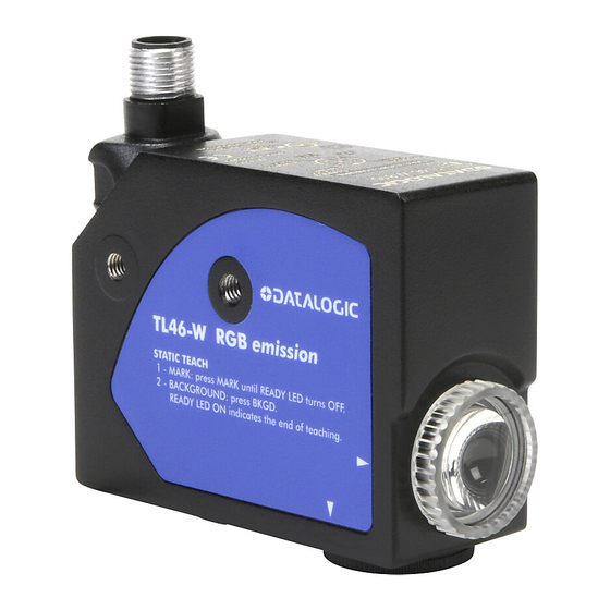
TL46-W
Contrast sensor
INSTRUCTION MANUAL
CONTROLS
OUT LED (yellow)
The red LED indicates the output status.
READY LED (green)
During functioning, the green LED permanently ON
indicates a normal operating condition; fast blinking
indicates an output overload condition.
PUSH-BUTTON (white)
The detection procedure is activated by pressing white
push-button.
See the "SETTING" paragraph for setup procedure indications.
INSTALLATION
The sensor can be positioned by means the two Ø3.5mm housing's holes
using or threaded M5 holes with 6mm max. depth.
Warning: the use of excessively long screws can damage the product.
The connector can be oriented at five different positions, rotating the block.
The position chosen is guaranteed by a mechanical blocking system.
The rotation can be carried-out even after sensor installation as the connector
block is completely self-contained inside the housing.
The operating distance is measured starting from the lens front face.
The reading direction can be changed inverting the cap and lens.
Mark detection on a reflective surface is improved adjusting the beam
direction to 5° ... 20° from surface axis.
DIMENSIONS
81.5
5.5
15.8
27.5
28
39.1
28
TECHNICAL DATA
Power supply:
10...30 Vdc limit values
Ripple:
2 Vpp max.
Current consumption
50 mA max. @ 24Vcc
(output current excluded):
1 PNP/NPN selectable output
Output:
30 Vdc max. (short-circuit protection)
(PNP is the default configuration)
Output current:
100 mA max.
≤ 2 V
Output saturation voltage:
33 μs
Response time:
Switching frequency:
15 kHz
Analogue output:
1 ... 3 V ± 10% (white 90%); 5.5 V max;
Analogue output
2.2 kΩ
impedance:
(short-circuit protection)
0 / 20 ms
Delay:
selectable via delay input
Dark/light selection
automatic
Indicators:
OUT LED (yellow) / READY LED (green)
Operating temperature:
-10 ... 55 °C
Storage temperature:
-20 ... 70 °C
Electric shock protection:
double insulation
Operating distance:
9 mm
± 3 mm
Depth of field:
Minimum spot dimension:
1.5x5 mm
blue (465 nm) / green (520 nm) / red (630 nm)
Emission type:
with automatic selection
Ambient light rejection:
according to EN 60947-5-2
0.5 mm amplitude, 10 ... 55 Hz frequency, for
Vibrations:
each axis (EN60068-2-6)
11 ms (30 G) 6 shock for each axis
Shock resistance:
(EN60068-2-27)
Housing material:
aluminium
Lens material:
PMMA
Mechanical protection:
IP67
Connections:
M12 5-pole connector
Weight:
170 g. max.
CONNECTIONS
CTi Automation - Phone: 800.894.0412 - Fax: 208.368.0415 - Web: www.ctiautomation.net - Email: info@ctiautomation.net
DETECTION (MARK-BACKGROUND)
- Position mark in front of the sensor light spot and press white
button until the READY LED (green) turns OFF.
The sensor detects the mark alternating the red, green and blue emissions.
Avoid mark movements during this phase.
15.5
- Position the background in front of the sensor light spot and press white
push-button again. The sensor detects the mark alternating the red, green
and blue emissions. Avoid background movements during this phase.
The DARK/LIGHT operating mode is automatically selected by the sensor.
Dark mark - light background = dark mode; light mark - dark background =
light mode.
If the READY LED is permanently ON, the detection is successful.
If the LED blinks slowly, the detection has failed due to insufficient contrast.
The sensor returns to the previous setting by pressing white
Repeat the procedure from the beginning.
PNP/NPN OUTPUT SETTING
The digital output can be PNP or NPN configured.
- To change output press white
- The setting is signalled by the status change of the READY LED.
If the READY LED turns off after a 1 sec. pressure, release push-button
only after the re-powering of the LED (10sec).
- The output setting is signalled by the READY LED. Releasing the push-
button, the READY LED blinks once if the PNP output is set, blinks twice if
the NPN output is set.
1 sec
pressure of
pressure of
OUTPUT OVERLOAD
The digital output overload is signalled by the rapid blinking of the READY
LED.
SETTING
ANALOGUE output
The analogue output supplies a voltage proportional to the signal received by
push-
the sensor. The voltage supplied is 1 ÷ 5.5V.
The maximum voltage is obtained with reflective objects; on 90% white the
voltage is equal to 3V.
DELAY SETTING
The DELAY extends to 20ms the minimum duration of the active output
allowing the slower interfacing systems to detect shorter pulses.
OUT without DELAY
OUT with DELAY
Delay activation
- Connect Delay signal (grey wire) to power supply.
Delay deactivation
- Connect Delay signal (grey wire) to 0V or leave unconnected.
push-button.
push-button for 10 sec.
EX-II-3DG IP67 T6
Temperature class:
Max. Power consumption 1500 mW at 30 Vdc
Max. Internal capacitance 450 pF
Internal inductance:
DECLARATION OF CONFORMITY
10 sec
Release of
We DATASENSOR S.p.A. declare under our sole responsibility that these products are conform to the
2004/108/CE, 2006/95/CE Directives and successive amendments.
push-buttons
WARRANTY
DATASENSOR S.p.A. warrants its products to be free from defects.
DATASENSOR S.p.A. will repair or replace, free of charge, any product found to be defective during the
warranty period of 36 months from the manufacturing date.
This warranty does not cover damage or liability deriving from the improper application of
DATASENSOR products.
DATASENSOR S.p.A. Via Lavino 265
40050 Monte S. Pietro - Bologna - Italy
Tel: +39 051 6765611
http://www.datasensor.com
DATASENSOR S.p.A. cares for the environment: 100% recycled paper.
DATASENSOR S.p.A. reserves the right to make modifications and improvements without
prior notification.
ACCESSORY FUNCTIONS
ON
OFF
ON
20ms
20ms
OFF
T6 (<85°C)
negligible
Fax: +39 051 6759324
e-mail: info@datasensor.com
826003062 Rev.D
Advertisement

Related Manuals for Datasensor TL46-W


Summary of Contents for Datasensor TL46-W
- Page 1 WARRANTY DATASENSOR S.p.A. warrants its products to be free from defects. DATASENSOR S.p.A. will repair or replace, free of charge, any product found to be defective during the warranty period of 36 months from the manufacturing date. This warranty does not cover damage or liability deriving from the improper application of DATASENSOR products.
- Page 2 DATASENSOR S.p.A. warrants its products to be free from defects. The DELAY extends to 20ms the minimum duration of the active output DATASENSOR S.p.A. will repair or replace, free of charge, any product found to be defective during the allowing the slower interfacing systems to detect shorter pulses.
- Page 3 DIMENSIONS PARAMETER SETTING - Position the background in front of the sensor light spot and press the Some parameters can be changed entering in the menu: DELAY ON, DELAY push-button again. The sensor detects the background and automatically 81.5 selects the best emission to detect the OFF, PNP/NPN switching output, display orientation and powering on/off of the display.
- Page 4 The parameters are saved pressing and releasing it the display returns to DATASENSOR S.p.A. will repair or replace, free of charge, any product found to be defective during the normal visualisation. warranty period of 36 months from the manufacturing date.
Need help?
Do you have a question about the TL46-W and is the answer not in the manual?
Questions and answers