Table of Contents
Advertisement
Quick Links
Advertisement
Table of Contents

Related Manuals for Bholanath BHSS-2500W-PARA


Summary of Contents for Bholanath BHSS-2500W-PARA
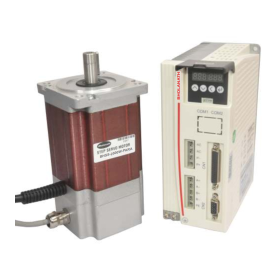
- Page 1 Parameter Setting & High Torque Step Servo BHSS - 2500W-PARA - P A R 0 0 W S - 2 5 B H S Parameter Setting Drive Step servo & motor are Note:- matched pair with BH-120VAC power supply Email : support@bholanath.in...
-
Page 2: Table Of Contents
® Bholanath Content www.bholanath.in COMMITTED TO PRECISION Foreword ............................3 ........................BHSS-2500W-PARA ............................1 Overview 1.1 Product Description ....................... 5 1.2 Feature ........................... 5 1.3 Application field ........................5 2 Performance Indicators ......................6 2.1 Electrical Characteristics ....................... -
Page 3: Foreword
® Bholanath www.bholanath.in COMMITTED TO PRECISION Foreword Thank you for using our easy servo drive. Before using this product, be sure to read the manual to learn the necessary safety information, precautions, and operating methods. Incorrect handling may lead to extremely serious consequences. -
Page 4: Committed To Precision
350RPM.The Step - Servo Motor BHSS - 2500 W-PARA gives more torque at lower RPM’s thus giving abetter performance than 2500 Watts Servo Motors as seen in the graph. TECHNICAL DATA BHOLANATH STEP SERVO MOTOR BHSS - 2500 W-PARA haracteristics SERVO MOTOR 2500 WATTS... -
Page 5: Overview
® Bholanath www.bholanath.in COMMITTED TO PRECISION 1 Overview 1.1 Product Description BHSS-1000W-PARA (Parameter) belongs to easy servo (servo-stepper) drives. With new generation of 32-bit DSP motor control technology, which completely overcomes the problem of lost step of open-loop stepping motor, BHSS-1000W-PARA greatly improves the high and low speed performance and torque utilization rate of stepping motor, and effectively reduces motor heat. -
Page 6: Performance Indicators
® Bholanath www.bholanath.in COMMITTED TO PRECISION 2 Performance Indicators 2.1 Electrical Characteristics BHSS-1000W-PARA Parameter Minimum value Typical value Maximum value Unit Continuous Output Current Input Supply Voltage Logic Input Current Logic Input Voltage Pulse Frequency MΩ Working Environment Cooling Method... -
Page 7: Installation
® Bholanath www.bholanath.in COMMITTED TO PRECISION 3 Installation Installation Size Back Side 139.2 BHSS-PTR Input supply Voltage: 110VAC Installation dimension drawing (unit: mm) Installation Method Install the drive with the upright side installation to create a strong air convection on the surface of the heat sink;... -
Page 8: Port And Wiring
® Bholanath www.bholanath.in COMMITTED TO PRECISION 4 Port and wiring 4.1 Wiring diagram Status indica on interface Button X4 Power input port Control signal port Motor output port Encoder input port Drive wiring diagram Note: Personnel involved in the wiring must have the professional ability. -
Page 9: Encoder Feedback Port
Bholanath www.bholanath.in COMMITTED TO PRECISION Note: Must use the matching BHOLANATH motor, if the user uses other motor and caused an accident, Bholanath shall not be responsible. 4.2.2 Encoder feedback port Encoder extension cable provided by Bholanath (please refer to 6.2 Encoder Extension... -
Page 10: Status Indicator
® Bholanath www.bholanath.in COMMITTED TO PRECISION outputting Encoder B channel positive outputting Encoder B channel negative outputting Encoder Z channel positive outputting Encoder Z channel negative outputting Encoder Z channel Encoder Z channel PZOut single-ended single-ended output output (output signal) In order to avoid some wrong actions and deviations, PU, DR and MF should meet certain requirements, as shown in the following figure:... -
Page 11: Menu Operation
® Bholanath www.bholanath.in COMMITTED TO PRECISION 5 Menu Operation 5.1 Operation interface There are four touch buttons on the PARA button display panel to achieve up, down, shift/cancel and confirm functions. As shown below: MS S3 Confirm Shi /Cancel Down... -
Page 12: System Monitor Menu Items Dp
® Bholanath www.bholanath.in COMMITTED TO PRECISION PA - dP - 5.2.1 System monitor menu items dP- dP- : Under this menu, ther’re total 12 second-level items, you can monitor 11 system State. Under the first-level menu, press to select dP–menu item. -
Page 13: 2Parameter Setting Menu Pa
® Bholanath www.bholanath.in COMMITTED TO PRECISION dP – VEr Software Version After entering the secondary menu, by press to select the item that you want to view the status, and then press the button, the display shows the status value. If you want to exit, press 5.2.2Parameter setting menu PA-... - Page 14 ® Bholanath www.bholanath.in COMMITTED TO PRECISION PA-common parameters list: ※ Name Function Default Range 0: Self-running (Triggered by pulse signal. When the pulse signal is turned on, the motor starts to run according to the parameter settings of PA-45 ~ PA-53;...
- Page 15 output level open selection 0 Alarm output ALM normally close 0 Pulse + direction mode Single and double PA-17 1 Double pulse mode 0/1/2 pulse selection 2 Orthogonal input Respond to the pulse when optocoupler turn from off to on. Pulse valid edge PA-18 selection...
- Page 16 ® Bholanath www.bholanath.in COMMITTED TO PRECISION details. holding time 0 microstep enable Pulse command PA-25 microstep enable 1 microstep disable Filter time = (PA-28) * 50us. This filter can change no acceleration and deceleration curve into a trapezoidal acceleration and deceleration...
-
Page 17: Parameter Management Menu Ee
® Bholanath www.bholanath.in COMMITTED TO PRECISION Speed feed forward PA-62 0~65535 coefficient Vibration damp PA-63 0~65535 coefficient In the point to point movement occasions, if there’s need for PA-64 Integral coefficient high positioning accuracy, 0~65535 please increase this value, increase it by 10 for each time. -
Page 18: Internal Test Menu Item Sr
® Bholanath www.bholanath.in COMMITTED TO PRECISION 5.2.4 Internal test menu item Sr- Level 1 menu Level 2 Function menu The internal test starts and the motor starts running at the Sr-On speed set by PA-45~PA-53. (Internal test) Sr-Off The internal test ends and the motor stops running. -
Page 19: Encoder Cable Specifications
® Bholanath www.bholanath.in COMMITTED TO PRECISION Encoder Cable Specifications The encoder cable is used to connect the motor encoder and drive. The figure below shows the encoder cable size drawing. The standard encoder cable length is 2m, and other specifications such as 3m, 4m, 5m, 8m, 9m, 10m, 12m, 14m are available. -
Page 20: Common Faults And Handling
® Bholanath www.bholanath.in COMMITTED TO PRECISION 7 Common faults and handling Caution: The drive and motor must be powered off for at least 5 minutes before touching the drive and motor to prevent electric shock and burns. After the drive fault alarm, it must be eliminated according to the alarm code before it can be put into use again. -
Page 21: Fault Analysis And Solution
® Bholanath www.bholanath.in COMMITTED TO PRECISION 7.2 Fault analysis and solution Error Error Causes Solution code name driver power input ① Use correct voltage ① voltage exceeds Increase the acceleration / ② specified value. Overvoltage deceleration time, reduce Err-2 The regenerative energy is ②... - Page 22 ® Bholanath www.bholanath.in COMMITTED TO PRECISION the closing and opening of electromagnetic brake the brake is not controlled by working circuit is correct. the S-OFF signal of the Control the motor brake ⑤ drive. via the S-OFF+, S-OFF- signals that come with the drive.
Need help?
Do you have a question about the BHSS-2500W-PARA and is the answer not in the manual?
Questions and answers