Table of Contents
Advertisement
Quick Links
Advertisement
Table of Contents

Related Manuals for Rondish Nexus Call System


Summary of Contents for Rondish Nexus Call System
- Page 1 Nexus Call System User Instructions V2.3.0, August 2022...
-
Page 2: Table Of Contents
NEXUS CALL SYSTEM by Rondish Contents 1. PRODUCT OVERVIEW ..........................5 1.1 Compatible Equipment ........................6 1.2 System Layout Options ........................10 1.2.1 Receiver Dongle & Over-Door Lights ..................11 1.2.2 Master & Network Repeaters ....................12 1.3 Site Testing ............................13 1.3.2 Pre-Install Survey ........................ - Page 3 NEXUS CALL SYSTEM by Rondish 2.6.2 Synch Sensory Devices with Monitor ..................34 2.7 Messaging ............................35 2.7.1 Configuring Nexus ........................36 2.7.2 Transmitter Setup ........................36 2.7.3 Pager Setup ..........................37 2.7.4 Remote Display Setup ....................... 38 2.7.5 Smartphones..........................40 3.
- Page 4 NEXUS CALL SYSTEM by Rondish...
-
Page 5: Product Overview
NEXUS CALL SYSTEM by Rondish PRODUCT OVERVIEW Nexus is a wireless call system designed for various applications including nurse and emergency call, assisted living, elderly care homes, rapid deploy for hospitals, and bathroom alarms. The system integrates emergency alarm call, wander prevention, bed alarms for fall management, and mobile calling devices for residents to wear on their wrist or around the neck. -
Page 6: Compatible Equipment
NEXUS CALL SYSTEM by Rondish 1.1 Compatible Equipment Model Description Image NDP-21 Rugged Tablet • Operate Nexus as a desktop touch screen • Connect either DON-30 or ZP-01(M) to establish a wireless network for your facility • Docking station (DOCK-01) includes three USB... - Page 7 NEXUS CALL SYSTEM by Rondish GP2009TR Paging Transceiver • Signals to data pagers • Used to receive signals for remote displays • Alarm escalation to supervisor or neighboring wards GP2009N Data Pager • Notifies nursing staff of active events •...
- Page 8 NEXUS CALL SYSTEM by Rondish TXP-11(V2) Patient Transmitter • Mobile call button for active residents • Wearable as wristband or pendant • Man-down alert in case of falls (wristband only) • Replaceable CR2450 lithium battery • Low battery indication •...
- Page 9 NEXUS CALL SYSTEM by Rondish CCP-01 Cordless Chair Sensorpad • Triggers alarm from patient chair exit • Paired with NGM-21 monitor • Durable and long-lasting • Low battery indication (from TM-11 transmitter module) CMAT-02 Cordless Floor Sensormat • Triggers alarm when stepped upon •...
-
Page 10: System Layout Options
NEXUS CALL SYSTEM by Rondish 1.2 System Layout Options Nexus uses a proprietary wireless format to direct signals from call points and sensory devices to a nurse station, where calls are displayed on the main Nexus panel. Once received, this panel can direct messaging to staff using a paging transmitter, where messages can be displayed on Remote displays, pagers or Android phones. -
Page 11: Receiver Dongle & Over-Door Lights
NEXUS CALL SYSTEM by Rondish 1.2.1 Receiver Dongle & Over-Door Lights Over-Door lights (ILB-21) receive local signals from a variety of calling units, and can either be configured as lights/sounder by reading into memory the calling unit, or configured as basic signal repeaters to extend system coverage. -
Page 12: Master & Network Repeaters
NEXUS CALL SYSTEM by Rondish 1.2.2 Master & Network Repeaters Medium to Large systems can be set up using a Master and Network Repeater (ZP-01(M) and ZP-01(S)) configuration. Each repeater has a range in excess of one mile in open space, and repeaters can be programmed to “hop”... -
Page 13: Site Testing
1.3 Site Testing Conducting a site survey can help you determine how many signal repeaters are needed for your facility, and ideal locations for them to be installed. Two pieces of equipment are available from Rondish for measuring effective range on site. -
Page 14: Pre-Install Survey
Rondish 1.3.2 Pre-Install Survey Rondish recommends using floor plans to propose locations for ZP-01(S) signal repeaters in corridors at regular intervals, around 40-50m apart. For a multi-story building operating as a single system, you can offset the positions of repeaters on different floors (if you don’t care about locating mobile alarms). The distances achievable will depend vary according to the structure of the building, with steel and concrete much lower than wood and drywall. -
Page 15: Installation
Nexus Event Log, which will be a number between 0-255. An RSSI value of 80 or above is OK, however Rondish recommends that readings below 100 be programmed to hop through a ZP-01(S) with a higher RSSI reading for the most reliable performance. You are allowed to hop through 2 x ZP-01(S) units (3 hops). -
Page 16: Full System Test
NEXUS CALL SYSTEM by Rondish 1.3.4 Full System Test Test all call points throughout the building. You can check the RSSI reading on the computer to see if any readings are low to give a guide, especially the pendant TXP-11 units. Keep a record of all test results for future reference. -
Page 17: Installation
Controller – Refer to section 2.2 for details. When all Repeaters in the network are initialized by the Master, power up or connection, check the RSSI values shown in the Event Log. Rondish recommends programming a signal hop if recorded RSSI values are below 100 4. -
Page 18: Master Station
NEXUS CALL SYSTEM by Rondish 2.1 Master Station Start your installation by powering up the device you will use for the Master Station. There are two current hardware options: 2.1.1 Station Hardware Nexus can operate on a Rugged Tablet (NDP-21) for an easily configurable desktop solution, or on a versatile Control Box (TVB-21) that allows a monitor or any size to be connected. - Page 19 NEXUS CALL SYSTEM by Rondish Nexus Control Box (TVB-21) Nexus Control Boxes can be configured with software to function as remote displays mounted on a wall or corridor. An ethernet port allows multiple stations to be networked with a central database. For details, see Section 2.5.3.
- Page 20 NEXUS CALL SYSTEM by Rondish Nexus Junction Box (NCON-11) The Nexus Junction Box (NCON-11) has been designed as a control box so that you can simply plug into the box the items that you require, including DON-30, ZP-01(M). It includes a TVB-21 to run Nexus – which can be connected to computer monitors of various sizes through an HDMI cable –...
- Page 21 NEXUS CALL SYSTEM by Rondish...
-
Page 22: Registering Nexus
Nexus will automatically launch when you connect a receiver dongle DON-30 or ZP-01(M) into the USB port of an Android device with the app installed. If you have purchased a device from Rondish it will come with Nexus pre-installed with a registered software license for your organization. If you are loading Nexus onto a device not purchased from Rondish you will be prompted to enter a registration key the first time Nexus is launched. -
Page 23: Configuring A Repeater Network
NEXUS CALL SYSTEM by Rondish 2.2 Configuring a Repeater Network Connect the ZP-01(M) into the Nexus controller and configure the network settings (refer to Section 3.6.4). The repeater units ZP-01(S) installed around the facility must match the Network ID and Frequency Channel selected for the Master. -
Page 24: Network Id
NEXUS CALL SYSTEM by Rondish Address dial, and enter the digit by pressing T-SW. Each time a digit is entered the ZP-01(S) will beep in acknowledgment. 2.2.1 Network ID The Network ID setting must be the same for all ZP-01(S) and ZP-01(M) communicating on the same Network. -
Page 25: Target Address
The RSSI value of the connection to the ZP-01(M) will be recorded in the Event Log, which will help installers determine whether a call point has a strong enough connection. Rondish recommends a value of >100 to ensure a reliable wireless network. - Page 26 NEXUS CALL SYSTEM by Rondish The chart below can be referred to when adjusting the rotary and DIP switches to set the required Address. ZPID Selection DIP-Switch Positions Rotary Switch 1: OFF 1: ON 1: OFF Code 2: OFF 2: OFF...
-
Page 27: Programming A Signal Hop
NEXUS CALL SYSTEM by Rondish 2.2.6 Programming a Signal Hop If the RSSI value of a Network Repeater shown in the Event log (Section 3.5) shows a value below 100, you may consider setting the target address to the ZPID of another ZP-01(S) to relay the signal to the central display. -
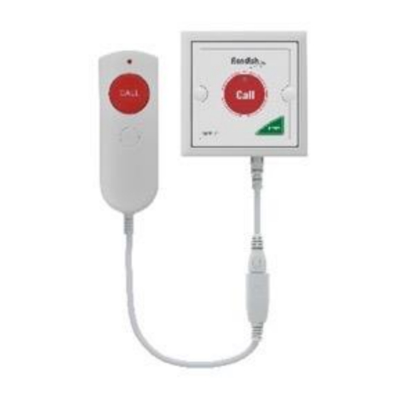
Page 28: Call Points
NEXUS CALL SYSTEM by Rondish 2.3 Call Points Nexus call points have minimal programming and installation required for a functional call system. Follow the steps below to configure call points: Step 1: Insert Batteries – Nexus call points come with batteries pre-installed. You will need to change these periodically based on usage. -
Page 29: Over-Door Lights
NEXUS CALL SYSTEM by Rondish 2.4 Over-Door Lights Over-Door lights provide a visual indication when a call is active in the area, have a buzzer with adjustable volume for audible indication, and will expand the wireless range of Nexus. Light Displays: White –... - Page 30 NEXUS CALL SYSTEM by Rondish Step 3: Enter pairing – Hold the Program button on the back of the ILB-21. The red and white sections will both stay ON to indicate the light is ready for pairing. Step 4: Read-in wireless devices – Trigger the device you want to add into memory.
-
Page 31: Doorwatcher
NEXUS CALL SYSTEM by Rondish 2.5 DoorWatcher DoorWatcher monitors offer protection against wandering from at-risk patients, especially useful for facilities with memory care residents. The monitors provide a visual alarm indication when a resident tag moves within range, can activate a door lock for delayed egress, and signal event details to Nexus for a caregiver to respond. -
Page 32: Adding Doorwatcher To Nexus
NEXUS CALL SYSTEM by Rondish Door Open timer – door monitor will alarm if the door remains open after this duration, whether a tag is present or not. To escort a resident through a door, trigger Reset before opening the door. The caregiver has 15s to open the door, at which point you will have this amount of time to pass through and close the door before triggering an alert. -
Page 33: Activate Patient Tags
NEXUS CALL SYSTEM by Rondish 2.5.4 Activate Patient Tags 2.5.5 Adjust Detection Distance - Default detection is ~1m... -
Page 34: Bedwatcher
NEXUS CALL SYSTEM by Rondish 2.6 BedWatcher Rondish NGM-21 CordFree monitors can be used with Nexus to provide bed/chair exit notifications; they also allow resetting of alarms from resident pendants or door/window sensors that are paired with the NGM-21. Sensor options for NGM-21 room controller •... -
Page 35: Messaging
NEXUS CALL SYSTEM by Rondish 2.7 Messaging Each Nexus Station can be programmed to send signals to data pagers and/or remote displays using POCSAG codes. The paging transmitter can be connected to a USB port on the Android device you are using to operate Nexus (See Section 2.1.1). -
Page 36: Configuring Nexus
GP2009TR paging repeater when used for remote displays. It is recommended to set one frequency channel for each system on site to avoid signal traffic. Product delivered from Rondish is centered on 450.375MHz, and should be kept within a band between 446.375MHz and 454.375MHz. -
Page 37: Pager Setup
NEXUS CALL SYSTEM by Rondish Baud Rate: 2400 bps Repeat message time: Disable Repeater: Disable (if you would like paging messages to be repeated at intervals, you can adjust this here) Avoid signal conflict: Enabled GP2009TR Settings 2.7.3 Pager Setup... -
Page 38: Remote Display Setup
Rondish 2.7.4 Remote Display Setup Remote displays ordered from Rondish will be pre-configured with a suitable software. Just connect a GP2009TR, along with a monitor using an HDMI cable, and alarms will display in a similar format as the Nexus Alarm Screen (Section 3.3) - Page 39 NEXUS CALL SYSTEM by Rondish Remote displays can be configured to display escalated or high-priority alarms from neighboring wards. Double-click or double-tap on the nurse icon to enter Remote Display configuration The chain icon indicates this display is connected with the Master Station. If you have lost connection this will appear in red as a broken chain.
-
Page 40: Smartphones
NEXUS CALL SYSTEM by Rondish Confirm new settings If additional Station IDs should display, add these as a separate task. Make sure to Save the tasks – the final column should have a green checkmark. 2.7.5 Smartphones This feature is available with the purchase of a Nexus Mobile license, and allows Android phones to be used for receiving and acknowledging messages. -
Page 41: Using Nexus
NEXUS CALL SYSTEM by Rondish 3. USING NEXUS Nexus was designed according to generally accepted principles of a nurse call system. Patient calls should be reset at location by the nurse or caregiver as soon as can reasonably be achieved. Nexus prioritizes alarms in several levels of importance, and there is a built-in record of events to aid management if there is an adverse event or response times are tracked over time. -
Page 42: Home Screen
NEXUS CALL SYSTEM by Rondish 3.2 Home Screen This is the default view of the application, and Nexus will return to this screen after alarms have been reset. Icons at show the Nexus screens The organization name can be configured in Settings (Section 3.6) -
Page 43: Alarm Screen
NEXUS CALL SYSTEM by Rondish 3.3 Alarm Screen The alarm screen will pop up when any event requires a response. If you tap on this icon when no alarms are present, the screen will be greyed out, and automatically return to the Home tab after several seconds. -
Page 44: Admin Reset
NEXUS CALL SYSTEM by Rondish Display Types & Priority Code Blue Priority 1 Emergency Priority 2 Man-down Priority 2 Bath Priority 3 Monitor* Priority 3 Priority 3 Chair Priority 3 Floor Priority 3 Door Priority 3 Pendant Priority 4 Call point... -
Page 45: Device Management
NEXUS CALL SYSTEM by Rondish 3.4 Device Management This tab is where you add/delete devices from Nexus, and define how each should display when an alarm is triggered. Tapping on Device Management will prompt the user for Full Access or Edit Only Mode. -
Page 46: Add New Device
NEXUS CALL SYSTEM by Rondish 3.4.1 Add New Device From this screen, triggering a device can have two effects: If Nexus does not already have this device in memory it will create a new entry with the 6-digit device ID, device type and notification that new hardware has been detected. -
Page 47: Delete Device
NEXUS CALL SYSTEM by Rondish If you want to change how the alarm is displayed you can just tap on the entry again to make amendments. 3.4.3 Delete Device If you need to remove something from memory, swipe left over the device. -
Page 48: Event Log
NEXUS CALL SYSTEM by Rondish 3.5 Event Log The Event Log will show the location, event type, time of initiation and duration of all events from the previous 24 hours. Alarms prior to the previous 24 hours will be stored in a data file that can be accessed by exporting and opening using Excel, or the complete log can be accessed by tapping the screen seven times. -
Page 49: Settings
NEXUS CALL SYSTEM by Rondish 3.6 Settings The Settings tab is where you will set the default name to display on the Home screen, change the Admin PIN, or export the data log. Pressing this tab requires inputting a 6-digit Admin PIN to access. If using Nexus for the first time the default code is 123456 3.6.1 Change Settings... -
Page 50: Backup/Restore
NEXUS CALL SYSTEM by Rondish Network Settings – used if system repeaters are connected (Section 3.6.4) • Network ID • Channel • Gateway ID Update – makes changes take effect 3.6.2 Backup/Restore After programming your system, the settings and Event log can be saved to a download folder and later exported to a USB drive. -
Page 51: Network Settings
These settings will only be visible if a ZP-01(M) is connected with Nexus, and allows the Network settings to be configured. If there are multiple networks operating on the same site Rondish recommends using different Network and Channel settings on each to ensure the systems do not affect the performance of each other. -
Page 52: Maintenance
Section 3.2.1). Regular maintenance will prevent an unexpected loss of functionality in your equipment. 4.1 Battery Life Rondish recommends changing batteries on a regular schedule to ensure that Nexus operates at an optimum level. The expected battery life of each component will depend on actual usage – the below table is given below for reference only, assuming each call lasts 1min before reset. -
Page 53: Troubleshooting
Forgotten PIN Contact your distributor for assistance • Other Visit YouTube/Rondish to view a product tutorial • Contact your local distributor for assistance... -
Page 54: Appendix: Fcc & Ce Statements
Hereby, Rondish Company Ltd declares that the above radio equipment types are in compliance with Directive 2014/53/EU. The full text of the EU declaration of conformity is available at the following internet address: www.rondish.com .
Need help?
Do you have a question about the Nexus Call System and is the answer not in the manual?
Questions and answers