Table of Contents
Advertisement
Quick Links
Advertisement
Table of Contents

Subscribe to Our Youtube Channel
Related Manuals for MB QUART Nautic NSB6V1


Summary of Contents for MB QUART Nautic NSB6V1
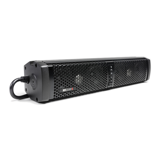
- Page 1 Quick Start Installation Guide Nautic NSB6V1 / NSB10V1 Soundbars...
- Page 2 Congratulations on your choice of MB Quart Nautic Sound Bars.This “Quick Start” Installation guide is meant to help you complete a basic installation. For more detailed information about the product, please visit our website at MBQuart.com Wiring The wiring and connections should be secure and away from any moving parts or extremely hot surfaces.
- Page 3 During unit power up, the blue LED on the bottom of the control panel will blink indicating that it is in Bluetooth search mode. During this process “MB Quart” should show up in your list of Bluetooth devices when the search has connected with your device. When the connection is made the blue LED will change to a solid color.
- Page 4 Maxxsonics consequential damages connected therewith. To view the full warranty, please visit the website. MB Quart products are designed and engineered in the USA by www.maxxsonics.com MBQ NAUTIC SBAR QSG 01 - rev1...
- Page 5 SOUND BAR MOUNTING The following is intended to help you mount the sound bar. We highly recommend employing the expertise of a professional installer. The sound bar has two convenient installation styles. Roll Cage and Surface Mount review this document to determine which you will use, then prepare for installation. A.
- Page 6 FIG 1-1 INSTALL STEPS - Surface Mount (L Brackets) Reference the illustration FIG 1-1 to confirm which components are needed for each STEP. Items on the list are called out with brackets [X]. STEP 1 - Mount 1 Surface Mount Bracket [6] per side with the longer [7] M5x20 screws. STEP 2 - Position the Sound Bar in place.
- Page 7 INSTALL STEPS - Roll Cage Reference the illustration FIG 1-1 to confirm which components are needed for each STEP. Items on the list are called out with brackets [X]. STEP 1 - Choose the appropriate Top Tube Clamp [1] for your roll cage diameter. We have included 1.5, 1.75 and 2 inch clamps.
- Page 8 ADDITIONAL MOUNTING OPTIONS If you find that your installation is more exotic or challenging that can be addressed with the included hardware we recommend our build partner AXIA ALLOYS. They offer a wide variety of billet aluminum mounts mounting system for more accessories that you can possibly install on your vehicle.
Need help?
Do you have a question about the Nautic NSB6V1 and is the answer not in the manual?
Questions and answers