Table of Contents
Advertisement
Quick Links
Advertisement
Table of Contents

Summary of Contents for VEGA POWER POWER CELL
- Page 1 PRODUCT BY...
- Page 2 INDICATORS COMPONENTS DEVICE (FRONT) DEVICE (RIGHT) DEVICE (LEFT) DEVICE SETTINGS SETTING UP DEVICE POWER CELL...
- Page 3 – Do not place the battery pack near a heat source, such as a fireplace. – Do not expose the battery pack to direct sunlight. – Do not allow the battery connectors to touch conductive objects such as wires. POWER CELL...
-
Page 4: Battery Handling Guide
• Do not impact, pull, drag or step on the battery pack. Do not subject it to any strong force. • Do not insert foreign objects into any part of the battery pack. • Do not use cleaning solvents to clean the battery pack. POWER CELL... -
Page 5: Leaking Batteries
Response to emergency situations The POWER CELL comprises multiple batteries that are designed to prevent hazards resulting from failures. However, VEGA POWER cannot guarantee their absolute safety. Leaking batteries If the battery pack leaks electrolyte, avoid contact with the leaking liquid or gas. - Page 6 fire. 3. If the battery pack has caught fire, do not try to extinguish the fire. Evacuate people immediately If the battery catches fire, it will produce noxious and poisonous gases. Do not approach. POWER CELL...
-
Page 7: Wet Batteries
Wet batteries If the battery pack is wet or submerged in water, do not try to access it. Contact VEGA POWER or your distributor for technical assistance. Damaged batteries Damaged batteries are dangerous and must be handled with extreme caution. -
Page 8: Specifications
Max. Charge/Discharge Current (A) 100A Communication Interface CAN,RS485 Configuration 16S1P 0〜50℃(Charge) -20〜50℃(Discharge) Working Temperature -20〜55℃(Storage) Lithium iron phosphate (LiFePO4) Cell chemistry ≥80% capacity state after 4800cycles at Cycle life 0.5C, 25 C, 100% DOD IP level IP 54 POWER CELL... - Page 9 Solid Green Blink Solid Green 50%-75% Solid Green Solid Green Solid Green Blink Solid Green Solid Green >75% Solid Green Solid Green Solid Green Solid Green Blink Solid Green Solid Green Solid Green Operating Solid Green Blink indicatort POWER CELL...
- Page 10 COMPONENTS Power Cell Installation manual Power Cell wire Battery Mount Wall Mount Anchor Bolts Lugs POWER CELL...
-
Page 11: Device (Front)
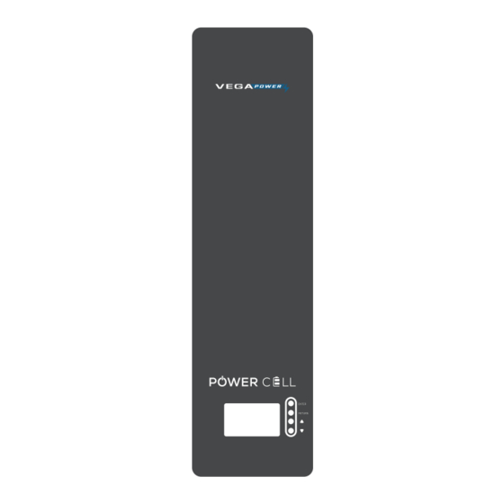
DEVICE (FRONT) LED Display Power button Display controls ENTER RETURN SCROLL UP SCROLL DOWN POWER CELL... - Page 12 DEVICE (RIGHT) RS485 ALARM RS485 *REFER TO FIG 1.0 POWER BATTERY V+(RED) BATTERY V+(RED) POWER CELL...
- Page 13 DEVICE (LEFT) Preasure Release Breaker Switch valve Earth Point Battery V- (BLACK) Battery V- (BLACK) POWER CELL...
-
Page 14: Device Settings
DEVICE SETTINGS RS485 communication DIP address should setup as the following table RS485 COMMUNICATION PACK 1 PACK 2 PACK 3 PACK 4 PACK 5 PACK 6 PACK 7 PACK 8 PACK 9 PACK 10 PACK 11 PACK 12 PACK 13 PACK 14 PACK 15... - Page 15 POWER CELL...
- Page 16 This warranty does not cover the cost of freight to return the unit to VEGA POWER. The sole and exclusive remedy for any unit found to be defective is repair or replacement, at the option of VEGA POWER.
- Page 17 WE GOT YOU POWERED +94 770 555 552 info@vegapower.lk vegapower.lk POWER CELL...

Need help?
Do you have a question about the POWER CELL and is the answer not in the manual?
Questions and answers