Table of Contents
Advertisement
Quick Links
865GVBMS/865GVBM
USER'S MANUAL
M/B For LGA 775 Pentium 4 Processor
NO. G03865GVBMR207
Rev:2.0
Release date: August 2005
Trademark:
* Specifications and Information contained in this documentation are furnished for information use only, and are
subject to change at any time without notice, and should not be construed as a commitment by manufacturer.
Advertisement
Table of Contents

Related Manuals for JETWAY 865GVBMS


Summary of Contents for JETWAY 865GVBMS
- Page 1 865GVBMS/865GVBM USER'S MANUAL M/B For LGA 775 Pentium 4 Processor NO. G03865GVBMR207 Rev:2.0 Release date: August 2005 Trademark: * Specifications and Information contained in this documentation are furnished for information use only, and are subject to change at any time without notice, and should not be construed as a commitment by manufacturer.
-
Page 2: Table Of Contents
TABLE OF CONTENT USER’S NOTICE ..........................ii MANUAL REVISION INFORMATION.................... ii COOLING SOLUTIONS........................ii CHAPTER 1 INTRODUCTION OF 865GVBMS/865GVBM MOTHERBOARD FEATURE OF MOTHERBOARD ..................1 SPECIFICATION........................2 PERFORMANCE LIST......................3 LAYOUT DIAGRAM & JUMPER SETTING..............4 CHAPTER 2 HARDWARE INSTALLATION HARDWARE INSTALLATION STEPS ................ -
Page 3: User's Notice
TRANSMITTED OR TRANSLATED INTO ANY LANGUAGE IN ANY FORM OR BY ANY MEANS WITHOUT WRITTEN PERMISSION OF THE MANUFACTURER. THIS MANUAL CONTAINS ALL INFORMATION REQUIRED TO USE 865GVBMS/865GVBM MOTHER- BOARD AND WE DO ASSURE THIS MANUAL MEETS USER’S REQUIREMENT BUT WILL CHANGE, CORRECT ANY TIME WITHOUT NOTICE. -
Page 4: Chapter 1 Introduction Of 865Gvbms/865Gvbm Motherboard
Introduction of 865GVBMS/865GVBM Motherboard 1-1 Feature of motherboard The 865GVBMS/865GVBM motherboard is design for use Intel Pentium 4 Processor in LGA775 (Land Grid Array) Socket Prescott Processor with the Intel 865GV Chipset delivers a high performance and professional desktop platform solution. Which utilize the design and the memory size expandable to 2.0GB. -
Page 5: Specification
150 MB/s ∗ VIA VT6106S PCI LAN controller chip LAN On Board ∗ Supports 10/100 Mb/sec data transfer rate (for 865GVBMS) ∗ Realtek ALC 6-channel AC97’ Codec integrated Audio ∗ Support 6-channel 3D surround & Positioning Audio ∗... -
Page 6: Performance List
1-3 Performance List The following performance data list is the testing result of some popular benchmark testing programs. These data are just referred by users, and there is no responsibility for different testing data values gotten by users (the different Hardware & Software configuration will result in different benchmark testing results.) Performance Test Report CPU:... -
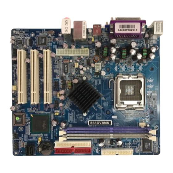
Page 7: Layout Diagram & Jumper Setting
1-4 Layout Diagram & Jumper Setting (for 865GVBMS) PRINT LINE-IN PS/2 Mouse PS/2 Keyboard LINE-OUT COM1 USB1 CPU Socket PS2 KB/Mouse Port FINTEK F71872F I/O Chip CPU FAN DDR DIMMx2 PC99 Back Panel Floppy Connector ATX 12V Power Connector USB Port (USB1) - Page 8 ATX 12V Power Connector 4-pin Block P.21 USB1, UL _ B USB Port Connector 4-pin Connector P.21 LAN Connectors RJ-45 Connector P.21 (for 865GVBMS) PS/2 Mouse & PS/2 Keyboard 6-pin Female P.21 (PS2 KB/MOUSE) Connector PARALLEL Parallel Port Connector 25-pin Female P.21...
-
Page 9: Chapter 2 Hardware Installation
Chapter 2 Hardware installation 2-1 Hardware installation Steps Before using your computer, you had better complete the following steps: 1. Check motherboard jumper setting 2. Install CPU and Fan 3. Install System Memory (DIMM) 4. Install Expansion cards 5. Connect IDE and Floppy cables, Front Panel /Back Panel cable 6. -
Page 10: Install Cpu
(2) Keyboard/USB Power On function Enabled/Disabled: JP2, JP3 When setting Enabled you can using keyboard by key in password/USB device to power on system. JP2 1-2 closed Keyboard/USB Power On Disabled (Default) JP2 2-3 closed Keyboard/USB Power On Enabled JP3 1-2 closed USB Power On Disabled (Default) JP3 2-3 closed USB Power On Enabled 2-3 Install CPU 2-3-1 Glossary... -
Page 11: About Intel Pentium 4 Lga775 Cpu
2-3-2 About Intel Pentium 4 LGA775 CPU This motherboard provides a 775-pin surface mount, LGA775 Land Grid Array socket, referred to as the LGA775 socket supports Intel Pentium 4 processor in the 775 Pin package utilizes Flip-Chip Land Grid Array (FC-LGA4) package technology. The CPU that comes with the motherboard should have a cooling FAN attached to prevent overheating. -
Page 12: Lga 775 Cpu Installation Guide
2-3-3 LGA 775 CPU Installation Guide Socket Preparation Opening the socket: Note: Apply pressure to the corner with right hand thumb while opening/closing the load lever, otherwise lever can bounce back like a “mouse trap” and WILL cause bent contacts (when loaded) Socket Load Plate Open... - Page 13 Visually inspect for bent contacts (Recommend at least 1stpass visual inspection) NOTE: Refer to the Handling and Inspection Module for 1stand 2ndpass inspection details. NOTE: Glove images are for illustrative purposes only. Please consult local safety guidelines for specific requirements NOTE: Recommend not to hold the load plate as a lever, instead hold at tab with left hand, removing the PnP cap with right hand...
- Page 14 775-Land Package Removal Open the Load Plate/Lever with both hands: With left hand index finger and thumb to support the load plate edge, engage PnP cap with right hand thumb and peel the cap from LGA775 Socket while pressing on center of PnP cap to assist in removal. Pick up 775-land LGA package: By Vacuum Pen: Place a minimum 9-mm cup at approximately the center of IHS.
- Page 15 Visually inspect socket contact array 1. First Pass Inspection Scan socket contact array at varying angles noting the presence of any foreign material If foreign material can’t be blown off by compressed air, or mechanical damage (Mode1 or 4) observed, reject the motherboard for further evaluation or socket replacement. 2.
- Page 16 NOTE: Thermal Solutions that come with IntelR boxed processor use pre-applied thermal interface material Apply Thermal and not grease. Interface Material Remove Heat Sink (HS) from packaging media Place HS onto the LGA775 Socket • Ensure fan cables are oriented on side closest to fan header •...
- Page 17 Intel Reference Thermal Solution Disassembly Rotate fastener cap. turn to un-lock Pull up fastener cap to un-seat 12 Disconnect fan cable from motherboard header Turn fastener caps (4) counter-clock wise 90degrees to the un-locked position • A flat-bladed screwdriver may be used if required Pull up on fastener caps to unseat Manually remove HS with gentle twist motion.
- Page 18 Remove the heatsink from the socket Gently push loose thermal interface material (TIM) to center of processor (pictures 2 and 3) Remove pieces with dry cloth (picture 4) Wipe with dry, lint-free cloth to remove most of the material (picture 5) Wet another lint-free cloth with isopropyl alcohol (IPA) and wipe to clean remaining material (picture 6) Be careful to remove material from gaps between processor and load plate...
- Page 19 Replacing Damaged Fasteners • To prevent damage, avoid setting the thermal solution with the prongs down − Set on heatsink side or with fan down • The plastic fasteners on the heatsink can be replaced. − Use Shop Intel to order spare fasteners −...
- Page 20 Damaged. Attempts to straighten not recommended Tilt to remove Replacing Fasteners • To replace the fastener − Start with the white prong − Note the “keying” notch feature − Tilt the prong to insert into the heatsink leg. − Holding the white prong without bending it, push the black pin on from the bottom until you hear a single “click”...
-
Page 21: Install Memory
Click Note: The black pin and white prong will only “snap” on in one orientation − Check to ensure the black pin is rotated properly for installation with the slot perpendicular to the heatsink 2-4 Install Memory This motherboard provides 184-pin DUAL INLINE MEMORY MODULES (DIMM) sites for memory expansion available from minimum memory size of 64MB to maximum memory size of 2.0GB DDR SDRAM. -
Page 22: Expansion Card
NOTE! When you install DIMM module fully into the DIMM socket the eject tab should be locked into the DIMM module very firmly and fit into its indention on both sides. WARNING! For the DDR SDRAM CLOCK is set at 200MHz, use only DDR400-compliant DDR Modules. -
Page 23: Interrupt Request Table For This Motherboard
2-5-3 Interrupt Request Table For This Motherboard Interrupt request are shared as shown the table below: INT A INT B INT C INT D INT E INT F INT G INT H √ Slot 1 √ Slot 2 √ Slot 3 √... - Page 24 USB Port connector: USB1, UL _ B (USB) The connectors are 4-pin connector that connect USB devices to the system board. LAN Port connector: LAN (for 865GVBMS) This connector is standard RJ45 connector for Network connector. PS/2 Mouse & PS/2 Keyboard Connector: KB (PS2 KB/MOUSE) The connectors for PS/2 keyboard and PS/2 Mouse.
- Page 25 PS/2 Mouse PRINT USB1 LINE-IN LINE-OUT PS/2 Keyboard COM1 (10) Floppy drive Connector (34-pin block): FDD This connector supports the provided floppy drive ribbon cable. After connecting the single plug end to motherboard, connect the two plugs at other end to the floppy drives. Pin 1 Floppy Drive Connector (11) Primary IDE Connector (40-pin block): IDE1...
-
Page 26: Headers
• Two hard disks can be connected to each connector. The first HDD is referred to as the “Master” and the second HDD is referred to as the “Slave”. • For performance issues, we strongly suggest you don’t install a CD-ROM or DVD-ROM drive on the same IDE channel as a hard disk. - Page 27 USB2 USB3 Pin 1 Pin 1 USB Port Headers Speaker connector: SPEAK This 4-pin connector connects to the case-mounted speaker. See the figure below. Power LED: PWRLED The Power LED is light on while the system power is on. Connect the Power LED from the system case to this pin.
- Page 28 CPUFAN SYSFAN1 SYSFAN2 FAN Headers IR infrared module Headers (5-pin) : IR This connector supports the optional wireless transmitting and receiving infrared module. You must configure the setting through the BIOS setup to use the IR function. Pin 1 IR infrared module Headers (10) CD Audio-In Headers (4-pin) : CDIN CDIN are the connectors for CD-Audio Input signal.
-
Page 29: Starting Up Your Computer
2-7 Starting Up Your Computer 1. After all connection are made, close your computer case cover. 2. Be sure all the switch are off, and check that the power supply input voltage is set to proper position, usually in-put voltage is 220V∼240V or 110V∼120V depending on your country’s voltage used. -
Page 30: Chapter 3 Introducing Bios
Chapter 3 Introducing BIOS The BIOS is a program located on a Flash Memory on the motherboard. This program is a bridge between motherboard and operating system. When you start the computer, the BIOS program gain control. The BIOS first operates an auto-diagnostic test called POST (power on self test) for all the necessary hardware, it detects the entire hardware device and configures the parameters of the hardware synchronization. -
Page 31: The Main Menu
3-3 The Main Menu Once you enter Award BIOS CMOS Setup Utility, the Main Menu (Figure 3-1) will appear on the screen. The Main Menu allows you to select from fourteen setup functions and two exit choices. Use arrow keys to select among the items and press <Enter> to accept or enter the sub-menu. -
Page 32: Standard Cmos Features
Load Optimized Defaults Use this menu to load the BIOS default values that are settings for optimal performances system operations. Load Standard Defaults Use this menu to load the BIOS default values that are factory settings for the stable performance system operation. Set Supervisor/User Password Use this menu to set User and Supervisor Passwords. -
Page 33: Advanced Bios Features
Time The time format is <hour><minute><second>. Primary Master/Primary Slave Secondary Master/Secondary Slave Press PgUp/<+> or PgDn/<–> to select Manual, None, Auto type. Note that the specifications of your drive must match with the drive table. The hard disk will not work properly if you enter improper information for this category. - Page 34 Anti-Virus Protection Allows you to choose the VIRUS Warning feature for IDE Hard Disk boot sector protection. If this function is enabled and someone attempt to write data into this area, BIOS will show a warning message on screen and alarm beep. Disabled (default) No warning message to appear when anything attempts to access the boot sector or hard disk partition table.
-
Page 35: Advanced Chipset Features
Typematic Rate (Chars/Sec) Sets the number of times a second to repeat a keystroke when you hold the key down. The settings are: 6, 8, 10, 12, 15, 20, 24, and 30. Typematic Delay (Msec) Sets the delay time after the key is held down before is begins to repeat the keystroke. The settings are 250, 500, 750, and 1000. -
Page 36: Dram Timing Settings
Video BIOS Cacheable Select Enabled allows caching of the video BIOS, resulting in better system performance. However, if any program writes to this memory area, a system error may result. The settings are: Enabled and Disabled. Memory Hole At 15M-16M You can reserve this area of system memory for ISA adapter ROM. -
Page 37: Integrated Peripherals
3-7 Integrated Peripherals CMOS Setup Utility – Copyright(C) 1984-2004 Award Software Integrated Peripherals > Onboard IDE Function Press Enter Item Help > Onboard Device Function Press Enter > Onboard Super IO Function Press Enter Init Display First PCI Slot Menu Level > Power Loss Function Always Off ↑... -
Page 38: Onboard Device Function
OnChip IDE Primary/Secondary The integrated peripheral controller contains an IDE interface with support for two IDE channels. Select Enabled to activate each channel separately. The settings are: Enabled and Disabled. Primary/Secondary Master/Slave PIO The four IDE PIO (Programmed Input/Output) fields let you set a PIO mode (0-4) for each of the four IDE devices that the onboard IDE interface supports. -
Page 39: Onboard Super Io Function
3-7-3 Onboard Super IO Function CMOS Setup Utility – Copyright(C) 1984-2004 Award Software Onboard Super IO Function Onboard FDD Controller Enabled Item Help Onboard Serial Port 1 3F8/IRQ4 Onboard Serial Port 2 Disabled UART Mode Select Normal Menu Level >> IR2 Duplex Mode Half Onboard Parallel Port... -
Page 40: Power Management Setup
3-8 Power Management Setup The Power Management Setup allows you to configure your system to most effectively save energy saving while operating in a manner consistent with your own style of computer use. CMOS Setup Utility – Copyright(C) 1984-2004 Award Software Power Management Setup ACPI Function Enabled... -
Page 41: Pm Timer Reload Events
Wake-Up on RTC Alarm This function is for setting date and time for your computer to boot up. During Disabled, you cannot use this function. During Enabled, choose the Date and Time Alarm: Date(of month) Alarm You can choose which month the system will boot up. Set to 0, to boot every day. Time(hh:mm:ss) Alarm You can choose what hour, minute and second the system will boot up. -
Page 42: Irq Resources
Reset Configuration Data Normally, you leave this field Disabled. Select Enabled to reset Extended System Configuration Data (ESCD) when you exit Setup if you have installed a new add-on and the system reconfiguration has caused such a serious conflict that the operating system can not boot. The settings are: Enabled and Disabled. -
Page 43: Pc Health Status
3-10 PC Health Status This section shows the Status of you CPU, Fan, Warning for overall system status. This is only available if there is Hardware Monitor onboard. CMOS Setup Utility – Copyright(C) 1984-2004 Award Software PC Health Status Shutdown Temperature Disabled Item Help Show PC Health in Post... -
Page 44: Miscellaneous Control
3-11 Miscellaneous Control This section is for setting CPU Frequency/Voltage Control. CMOS Setup Utility – Copyright(C) 1984-2004 Award Software Miscellaneous Control CPU Clock Ratio Item Help Auto Detect PCI Clk Enabled Spread Spectrum Disabled ** Current Host Clock is 100MHz ** Menu Level >... -
Page 45: Load Standard/Optimized Defaults
3-12 Load Standard/Optimized Defaults Load Standard Defaults When you press <Enter> on this item, you get confirmation dialog box with a message similar Load Standard Defaults (Y/N)? N Pressing <Y> loads the BIOS default values for the most stable, minimal-performance system operations. -
Page 46: Chapter 4 Driver & Free Program Installation
2. VGA install Intel 865GV VGA driver 3. SOUND install ALC AC97’ Codec Audio driver 4. LAN install VIA 6105/6106S LAN Controller driver (only for 865GVBMS) 5. USB2.0 install USB 2.0 driver 6. PC-CILLIN install PC-CILLIN2004 anti-virus program 7. PC-HEALTH install Intel Hardware Doctor Utility 8. -
Page 47: Inf Install Intel 865Gv Chipset System Driver
4-1 INF install Intel 865GV chipset system driver After you have completed the installation of your operation system (WINDOWS 98SE). You will find an UNKNOWN DEVICE in the device manager (START/SETTING/CONTROL PANEL/ SYSTEM/DEVICE MANAGER). You have to install INF driver as shown below: 1. -
Page 48: Sound Install Alc Ac97' Codec Audio Driver
Click YES, This is Announce CopyRight If You Want Re-start Computer , Click FINISH 4-3 SOUND install ALC AC97’ Codec Audio Driver 1. Click SOUND when MAGIC INSTALL 2. Then auto detect operation system language MENU appears edition, click OK, start to install DRIVER 3. -
Page 49: Lan Install Via 6105/6106S Lan Controller Driver
DVD\CD-ROM drives to Enabled digital CD Audio for the CD-ROM Device when use the SPDIF-Out digital signal. 4-4 LAN install VIA 6105/6106S LAN Controller Driver (only for 865GVBMS) WINDOWS 98SE/98ME/2000/XP Setup 1. Click LAN when Magic Install Menu appear 2. Install VIA VT6105 PCI 10/100M Fast... -
Page 50: Usb2.0
4-5 USB2.0 install Intel USB2.0 Driver Windows 98SE/ME USB 2.0 Driver installation 1. Click USB2.0 when Magic Install Menu 2. This license agreement appear, click Yes, then finish appear install driver , click Close and restart your computer Windows 2000/XP USB 2.0 Driver installation Windows 2000 Mothed1 Start Windows 2000 OS and Internet Connect, Select "Windows Update", Select Driver Update, Install Windows2000 USB2.0 Driver... -
Page 51: Mbios&Dx9 Install Bios Live Update Utility And Directx9
3. Select Finish after setup complete 4. Execute MY GUARD utility, On-time Monitoring your system health NOTE: MAGIC INSTALL will auto detect file path X:\INTEL865\HEALTH\SETUP.EXE This driver supports WINDOWS 95/98/98SE/NT4.0/2000 4-7 MBIOS&DX9 Install BIOS Live Update Utility and DIRECTX9 1. Click Magic BIOS when Magic Install MENU 2. - Page 52 5. When On-line update BIOS the program will 6. Click Next if you need update BIOS, after auto-check your BIOS version upgrade BIOS, the system will clear CMOS and automatically restart Click Yes if you want to update the BIOS When System programming BIOS don’t turn otherwise choose No to exit off power, after finish update BIOS, the system...
-
Page 53: Pc-Cillin Install Pc-Cillin2004 Anti-Virus Program
4-8 PC-CILLIN Install PC-CILLIN 2004 Anti-virus program Click PC-CILLIN when MAGIC INSTALL Click NEXT when the "Trend Micro internet MENU appear security" installshield wizard windows appear This is license agreement, select "I Accept Click NEXT and Enter your Customer the terms" and Click NEXT Information, Click NEXT or choose Change to change the path for the file to be stored Click INSTALL, Start to install the software... -
Page 54: How To Update Bios
STEP 2. Copy utility program to your boot disc. You may copy from DRIVER CD X:\FLASH\AWDFLASH.EXE or download from our web site. STEP 3. Copy latest BIOS for 865GVBMS/865GVBM from our web site to your boot disc. STEP 4. Insert your boot disc into A:, start the computer, type “Awdflash A:\865GVBMSAxxx.BIN /SN/PY/CC/R”...
Need help?
Do you have a question about the 865GVBMS and is the answer not in the manual?
Questions and answers