Table of Contents
Advertisement
Quick Links
845E4/845E4L
USER'S MANUAL
M/B For Socket 478 Pentium 4 Processor
NO. G03-845E4R1A
Release date: February 2003
Trademark:
* Specifications and Information contained in this documentation are furnished for information use only, and are
subject to change at any time without notice, and should not be construed as a commitment by manufacturer.
Advertisement
Table of Contents

Related Manuals for JETWAY 845E4


Summary of Contents for JETWAY 845E4
- Page 1 845E4/845E4L USER'S MANUAL M/B For Socket 478 Pentium 4 Processor NO. G03-845E4R1A Release date: February 2003 Trademark: * Specifications and Information contained in this documentation are furnished for information use only, and are subject to change at any time without notice, and should not be construed as a commitment by manufacturer.
-
Page 2: Table Of Contents
TABLE OF CONTENT USER’S NOTICE ....................... ii MANUAL REVISION INFORMATION................ii COOLING SOLUTIONS ....................ii CHAPTER 1 INTRODUCTION OF 845E4/845E4L MOTHERBOARD 1-1 FEATURE OF MOTHERBOARD................1 1-2 SPECIFICATION....................2 1-3 PERFORMANCE LIST..................3 1-4 LAYOUT DIAGRAM & JUMPER SETTING............4 CHAPTER 2 HARDWARE INSTALLATION 2-1 HARDWARE INSTALLATION STEPS.............. -
Page 3: User's Notice
TRANSMITTED OR TRANSLATED INTO ANY LANGUAGE IN ANY FORM OR BY ANY MEANS WITHOUT WRITTEN PERMISSION OF THE MANUFACTURER. THIS MANUAL CONTAINS ALL INFORMATION REQUIRED TO USE 845E4/845E4L MOTHER-BOARD AND WE DO ASSURE THIS MANUAL MEETS USER’S REQUIREMENT BUT WILL CHANGE, CORRECT ANY TIME WITHOUT NOTICE. -
Page 4: Chapter 1 Introduction Of 845E4/845E4L Motherboard
ULTRA ATA 100 to provide speedier HDD throughout that boosts overall system performance. 845E4/845E4L provided an AGP 4X slot on the motherboard (For 1.5V AGP card only. No for 3.3V or Universal AGP card). This AGP slot will support either a 4X VGA card or Intel Digital Video Out ports add support for digital displays and TV-out. -
Page 5: Specification
∗ Reserves support for future Intel Pentium 4 processors ∗ 184-pin DDR SDRAM module socket x2 Memory Socket ∗ Support DDR266 DRAM for 845E4/845E4L ∗ Expandable to 2.0GB ∗ AGP slot x1 for AGP 1.5V standard only, support AGP 2.0 &... -
Page 6: Performance List
1-3 Performance List The following performance data list is the testing result of some popular benchmark testing programs. These data are just referred by users, and there is no responsibility for different testing data values gotten by users (the different Hardware & Software configuration will result in different benchmark testing results.) Performance Test Report Intel Pentium 4 1.9GHz mPGAB package... -
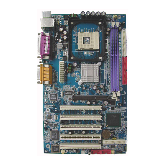
Page 7: Layout Diagram & Jumper Setting
1-4 Layout Diagram & Jumper Setting (for 845E4L) PRINT GAME/MIDI PORT PS/2 Mouse PS/2 Keyboard LINE-IN COM1 COM2 LINE-OUT K/B Power ON Jumper CPU Socket (JP1) CPU FAN PS2 KB/Mouse Port USB Port /LAN Connector (for 845E4L) ATX 12V Power Conn. DDR DIMM X2 PC99 Back Panel ATA 100 IDE Conn. - Page 8 Jumpers Jumper Name Description Page CPU Frequency Select 4-pin Block CMOS RAM Clear 3-pin Block Keyboard Power On Enable/Disabled 3-pin Block Connectors Connector Name Description Page ATXPWR ATX Power Connector 20-pin Block P.13 ATX12V ATX 12V Power Connector 4-pin Block P.13 PS/2 Mouse &...
-
Page 9: Chapter 2 Hardware Installation
Hardware installation 2-1 Hardware installation Steps Before using your computer, you had better complete the following steps: 1. Check motherboard jumper setting 2. Install CPU and Fan 3. Install System Memory (DIMM) 4. Install Expansion cards 5. Connect IDE and Floppy cables, Front Panel /Back Panel cable 6. -
Page 10: Install Cpu
2. Forget password 3. After over clocking system boot fail 1-2 closed Normal (Default) 2-3 closed Clear CMOS CMOS RAM Clear Setting (3) Keyboard Power On function Enabled/Disabled: JP1 When setting Enabled you can using keyboard by key in password to power on system. 1-2 closed K/B Power ON Disable 2-3 closed K/B Power ON Enabled... -
Page 11: Glossary
2-3-1 Glossary Chipset (or core logic) - two or more integrated circuits which control the interfaces between the system processor, RAM, I/O devises, and adapter cards. Processor slot/socket - the slot or socket used to mount the system processor on the motherboard. -
Page 12: Install Memory
This motherboard provides a 478-pin surface mount, Zero Insertion Force (ZIF) socket, referred to as the mPGA478B socket supports Intel Pentium 4 processor in the 478 Pin package utilizes Flip-Chip Pin Grid Array (FC-PGA2) package technology. The CPU that comes with the motherboard should have a cooling FAN attached to prevent overheating. -
Page 13: Expansion Card
Make sure the installed memory are DDR266 SDRAM support 133MHz NOTE! memory clock, otherwise the system may hang during startup. Generally, installing DDR SDRAM modules to your motherboard is very easy, you can refer to figure 2-4 to see what a 184-Pin DDR200/DDR266 DDR SDRAM module looks like. Figure 2-4 NOTE! When you install DIMM module fully into the DIMM socket the eject tab should... -
Page 14: Interrupt Request Table For This Motherboard
Some expansion cards need an IRQ to operate. Generally, an IRQ must exclusively assign to one use. In a standard design, there are 16 IRQs available but most of them are already in use. Standard Interrupt Assignments Priority Standard function System Timer Keyboard Controller Programmable Interrupt... -
Page 15: Connectors, Headers
Do not use AGP 2X card (3.3V) in this motherboard. It will burn and damage the motherboard due to Intel® 845 chipset can not support AGP 2X (3.3V). The AGP Slot also supports AGP Digital Display Card for digital display and TV-out. IMPORTANT! Before you plug-in AGP card, please make sure the following notice is fully understood and practiced. - Page 16 Power Connector (20-pin block) : ATXPWR ATX Power Supply connector. This is a new defined 20-pins connector that usually comes with ATX case. The ATX Power Supply allows to use soft power on momentary switch that connect from the front panel switch to 2-pins Power On jumper pole on the motherboard.
- Page 17 Parallel Port connector is a 25-pin D-Subminiature Receptacle connector. The On- board Parallel Port can be disabled through the BIOS SETUP. Please refer to Chapter 3 “INTEGRATED PERIPHERALS SETUP” section for more detail information. Audio and Game Connector : L _ OUT, L _ IN, MIC, GAME This Connector are 3 phone Jack for LINE-OUT, LINE-IN, MIC and a 15-pin D-Subminiature Receptacle Connector for joystick/MIDI Device.
-
Page 18: Headers
This connector supports the provided IDE hard disk ribbon cable. After connecting the single plug end to motherboard, connect the two plugs at other end to your hard disk(s). If you install two hard disks, you must configure the second drive to Slave mode by setting its jumpers accordingly. - Page 19 (1) USB Port Headers (9-pin) : USB2, USB3 These headers are used for connecting the additional USB port plug. By attaching an option USB cable, your can be provided with two additional USB plugs affixed to the back panel. USB2 USB3 Pin 1 Pin 1...
- Page 20 SPEAK VCC 5 G ND SPKR Pin 1 Pin 1 System Case Connections Wake On-LAN Headers (3-pin) : WOL This connector connects to a LAN card with a WAKE ON-LAN output. This connector power up the system when a wake up signal is received through the LAN card. NOTE: This feature requires that Wake On LAN or Ring In Wake up is enabled.
- Page 21 (10) IR infrared module Headers (5-pin) : IR This connector supports the optional wireless transmitting and receiving infrared module. You must configure the setting through the BIOS setup to use the IR function. Pin 1 IR infrared module Headers (11) CD Audio-In Headers (4-pin) : CDIN CDIN are the connectors for CD-Audio Input signal.
-
Page 22: Starting Up Your Computer
2-7 Starting Up Your Computer 1. After all connection are made, close your computer case cover. 2. Be sure all the switch are off, and check that the power supply input voltage is set to proper position, usually in-put voltage is 220V∼240V or 110V∼120V depending on your country’s voltage used. -
Page 23: Chapter 3 Introducing Bios
Chapter 3 Introducing BIOS The BIOS is a program located on a Flash Memory on the motherboard. This program is a bridge between motherboard and operating system. When you start the computer, the BIOS program gain control. The BIOS first operates an auto-diagnostic test called POST (power on self test) for all the necessary hardware, it detects the entire hardware device and configures the parameters of the hardware synchronization. -
Page 24: The Main Menu
3-3 The Main Menu Once you enter Award BIOS CMOS Setup Utility, the Main Menu (Figure 3-1) will appear on the screen. The Main Menu allows you to select from fourteen setup functions and two exit choices. Use arrow keys to select among the items and press <Enter> to accept or enter the sub-menu. -
Page 25: Standard Cmos Features
Load Optimized Defaults Use this menu to load the BIOS default values that are settings for optimal performances system operations. Load Standard Defaults Use this menu to load the BIOS default values that are factory settings for the stable performance system operation. Set Supervisor/User Password Use this menu to set User and Supervisor Passwords. -
Page 26: Advanced Bios Features
The time format is <hour><minute><second>. Primary Master/Primary Slave Secondary Master/Secondary Slave Press PgUp/<+> or PgDn/<–> to select Manual, None, Auto type. Note that the specifications of your drive must match with the drive table. The hard disk will not work properly if you enter improper information for this category. - Page 27 Allows you to choose the VIRUS Warning feature for IDE Hard Disk boot sector protection. If this function is enabled and someone attempt to write data into this area, BIOS will show a warning message on screen and alarm beep. Disabled (default) No warning message to appear when anything attempts to access the boot sector or hard disk partition table.
-
Page 28: Advanced Chipset Features
Keystrokes repeat at a rate determined by the keyboard controller. When enabled, the typematic rate and typematic delay can be selected. The settings are: Enabled/Disabled. Typematic Rate (Chars/Sec) Sets the number of times a second to repeat a keystroke when you hold the key down. The settings are: 6, 8, 10, 12, 15, 20, 24, and 30. -
Page 29: Dram Timing Settings
Select Enabled allows caching of the video BIOS, resulting in better system performance. However, if any program writes to this memory area, a system error may result. The settings are: Enabled and Disabled. Memory Hole At 15M-16M You can reserve this area of system memory for ISA adapter ROM. When this area is reserved, it cannot be cached. -
Page 30: Integrated Peripherals
CMOS Setup Utility – Copyright(C) 1984-2003 Award Software Integrated Peripherals > Onboard IDE Function Press Enter Item Help > Onboard Device Function Press Enter > Onboard Super IO Function Press Enter Init Display First PCI Slot Menu Level > Power On Function Button Only KB Power On Password Enter... -
Page 31: Onboard Device Function
The integrated peripheral controller contains an IDE interface with support for two IDE channels. Select Enabled to activate each channel separately. The settings are: Enabled and Disabled. Primary/Secondary Master/Slave PIO The four IDE PIO (Programmed Input/Output) fields let you set a PIO mode (0-4) for each of the four IDE devices that the onboard IDE interface supports. -
Page 32: Onboard Super Io Function
Select Enabled if your system contains a Universal Serial Bus (USB) controller and you have a USB peripherals. The settings are: Enabled, Disabled. USB Keyboard Legacy Support Select Enabled if your system contains a Universal Serial Bus (USB) controller and you have a USB keyboard. -
Page 33: Power Management Setup
To operate the onboard parallel port as Standard Parallel Port only, choose “SPP.” To operate the onboard parallel port in the EPP modes simultaneously, choose “EPP.” By choosing “ECP”, the onboard parallel port will operate in ECP mode only. Choosing “ECP+EPP” will allow the onboard parallel port to support both the ECP and EPP modes simultaneously. -
Page 34: Pm Timer Reload Events
Blank Screen This option only writes blanks to the video buffer. V/H SYNC+Blank This selection will cause the system to turn off the vertical and horizontal synchronization ports and write blanks to the video buffer. Modem Use IRQ This determines the IRQ in which the MODEM can use. The settings are: 3, 4, 5, 7, 9, 10, 11, NA. -
Page 35: Irq Resources
Interconnect, is a system which allows I/O devices to operate at speeds nearing the speed the CPU itself uses when communicating with its own special components. This section covers some very technical items and it is strongly recommended that only experienced users should make any changes to the default settings. -
Page 36: Pc Health Status
CMOS Setup Utility – Copyright(C) 1984-2003 Award Software IRQ Resources IRQ-3 assigned to PCI Device Item Help IRQ-4 assigned to PCI Device IRQ-5 assigned to PCI Device IRQ-7 assigned to PCI Device Menu Level >> IRQ-9 assigned to PCI Device IRQ-10 assigned to PCI Device... -
Page 37: Miscellaneous Control
3-11 Miscellaneous Control This section is for setting CPU Frequency/Voltage Control. CMOS Setup Utility – Copyright(C) 1984-2003 Award Software Miscellaneous Control CPU Clock Ratio Item Help Auto Detect PCI Clk Enabled Spread Spectrum Disabled ** Current Host Clock is 100/33MHz ** Menu Level >... -
Page 38: Set Supervisor/User Password
Load Standard Defaults When you press <Enter> on this item, you get confirmation dialog box with a message similar Load Standard Defaults (Y/N)? N Pressing <Y> loads the BIOS default values for the most stable, minimal-performance system operations. Load Optimized Defaults When you press <Enter>... -
Page 39: Magic Install Supports Windows 95/98/98Se/Nt4.0/2000/Xp
Check your package and there is A MAGIC INSTALL CD included. This CD consists of all DRIVERS you need and some free application programs and utility programs. In addition, this CD also include an auto detect software which can tell you which hardware is installed, and which DRIVERS needed so that your system can function properly. -
Page 40: Sound Install Cmi Audio Codec Driver
shown below: 1. Click INF in the MAGIC INSTALL MENU 2. Click NEXT when Chipset Software Install Utility appears 3. This chart shows motherboards supported 4. Select if you want computer re-started by the driver click Yes click Finish NOTE: MAGIC INSTALL will auto detect file path X:\INTEL845\INF\SETUP.EXE This driver supports WINDOWS 95/98/98SE/ME/2000/XP (NT4.0 do not require) 4-2 SOUND Install CMI Audio Codec Driver... - Page 41 Click SOUND when MAGIC INSTALL Choose Install component in Installation MENU appears Package 3. Click Next when copyright Issue appears, click 4. Enter Program folders name or click Next Next or choose BROWSE to change the path for the file to be store 5.
-
Page 42: Install Via Vt6105 Pci 10/100Mb Fast Ethernet Driver
7. C-Media Media Rack Play table 8. C-Media Audio Configuration setting 9. C-Media Multi-Channel Audio Demo Program, 10. When Enabled XeaR, you can plug earphone you can Test speaker position in Speak-Out connector as a Rear speaker, and 2-channel speaker plug in Line-In as Front Speaker to get 4-channel effect 4-3 LAN Install VIA VT6105 PCI 10/100MB Fast Ethernet Driver WINDOWS 98SE/98ME/2000/XP Setup... -
Page 43: Intel 845 Pc-Health Monitor
Select YES and Restart your computer X:\RTLLAN\WIN98 (If OS is win9X) 4-4 PC-HEALTH Intel 845 PC-Health Monitor The path of the file is X:\INTEL845\HW30\SETUP.EXE (Only support WINDOWS 95/98/98SE/ME) In Windows 95/98 Winbond Hardware Doctor Monitoring Software needs some system files to copy in Utility that’s why it needs install PC-HEALTH twice to complete setup. -
Page 44: How To Utilize Pc-Health
4-4-1 How To Utilize PC-HEALTH 1. Click Program → Winbond Hardware Doctor 2. After executing Winbond Hardware Doctor it → Hardware Doctor the Winbond Hardware supports system voltage, Fan speed and Doctor will appears CPU/SYSTEM Temperature. Because this is You can remove the Utility in Control Panel a On-time Monitoring program therefore the →... - Page 45 After finish Setup you will have a Magic Double click the Magic BIOS icon you will BIOS icon in your screen have this picture, choose from internet you can upgrade BIOS On-line When On-line update BIOS the program Click Next if you need update BIOS, after will auto-check your BIOS version upgrade BIOS, the system will clear CMOS and automatically restart...
-
Page 46: Install Pc-Cillin2002 Anti-Virus Program
When choose From Local Driver to update 10. Choose the correct BIOS file to update BIOS BIOS, you must have the correct BIOS file in your Local Driver 4-6 IAA Install Application Accelerator Software The Intel Application Accelerator is designed to improve performance of the storage sub-system and overall system performance. - Page 47 3. This is license agreement, select "I Accept 4. Click NEXT and Enter your Customer the terms" and Click NEXT Information, Click NEXT or choose Change to change the path for the file to be stored 5. Click INSTALL, Start to install the software 6. Setup Complete and click FINISH 7.
-
Page 48: How To Disable On-Board Sound
You may copy from DRIVER CD X:\FLASH\AWDFLASH.EXE or download from our web site. STEP 3. Copy latest BIOS for 845E4/845E4L from our web site to your boot disc. STEP 4. Insert your boot disc into A:, start the computer, type “Awdflash A:\845E4Axxx.BIN /SN/PY/CC/R”...
Need help?
Do you have a question about the 845E4 and is the answer not in the manual?
Questions and answers