Table of Contents
Advertisement
Quick Links
849BS
USER'S MANUAL
M/B For Socket-A Athlon/Duron Processor
NO. G03-849BSR1A
Release date: April 2001
** Year 2000 compliant **
Trademark:
* Specifications and Information contained in this documentation are furnished for information use only, and are
subject
to change at any time without notice, and should not be construed as a commitment by manufacturer.
Advertisement
Table of Contents

Related Manuals for JETWAY 849BS


Summary of Contents for JETWAY 849BS
- Page 1 849BS USER'S MANUAL M/B For Socket-A Athlon/Duron Processor NO. G03-849BSR1A Release date: April 2001 ** Year 2000 compliant ** Trademark: * Specifications and Information contained in this documentation are furnished for information use only, and are subject to change at any time without notice, and should not be construed as a commitment by manufacturer.
-
Page 2: Table Of Contents
TABLE OF CONTENT USER’S NOTICE................1 MANUAL REVISION INFORMATION..........2 THERMAL SOLUTIONS..................2 CHAPTER 1 INTRODUCTION OF 849BS MOTHERBOARD 1-1 FEATURE OF MOTHERBOARD...............3 1-2 SPECIFICATION...................4 1-3 PERFORMANCE LIST.................5 1-4 LAYOUT DIAGRAM & JUMPER SETTING..........6 CHAPTER 2 HARDWARE INSTALLATION 2-1 HARDWARE INSTALLATION STEPS............8 2-2 CHECKING MOTHERBOARD'S JUMPER SETTING......8 2-3 INSTALL CPU....................9... - Page 3 3-9 PNP/PCI CONFIGURATION SETUP............36 3-9-1 IRQ RESOURCES..................3-10 PC HEALTH STATUS.................37 3-11 MISCELLANEOUS CONTROL ..............38 3-12 LOAD STANDARD/OPTIMIZED DEFAULTS........39 3-13 SET SUPERVISOR/USER PASSWORD............39 CHAPTER 4 DRIVER & FREE PROGRAM INSTALLATION MAGIC INSTALL SUPPORTS WINDOWS 95/98/98SE/NT4.0/2000....40 4-1 AGPVXD ........41 INSTALL ALI VGA AGPVXD DRIVER 4-2 IDE .............42 INSTALL ALI IDE DRIVER...
-
Page 4: User's Notice
MAY BE REPRODUCED, TRANSMITTED OR TRANSLATED INTO ANY LANGUAGE IN ANY FORM OR BY ANY MEANS WITHOUT WRITTEN PERMISSION OF MANUFACTURER. THIS MANUAL CONTAINS ALL INFORMATION REQUIRED TO USE 849BS MOTHER- BOARD AND WE DO ASSURE THIS MANUAL MEETS USER’S REQUIREMENT BUT WILL CHANGE, CORRECT ANY TIME WITHOUT NOTICE. -
Page 5: Chapter 1 Introduction Of 849Bs Motherboard
Maximum T case requirement. In addition, this collection is not intended to be a comprehensive listing of all heatsinks that support AMD processors. For vendor list of heatsink and fan, please visit: http://www1.amd.com/products/duron/thermals http://www1.amd.com/products/athlon/thermals Chapter 1 Introduction of 849BS Motherboard... -
Page 6: Feature Of Motherboard
1-1 Feature of motherboard The 849BS motherboard is design for use AMD Athlon / Duron processors, which utilize the SocketA design and the memory size expandable to 1GB. This motherboard use the newest ALi M1649 chipset, whose front side bus (133MHz/... -
Page 7: Performance List
Clock Generator Support 100/133MHz Front Side Bus Clock (CPU Bus clock) Support 100/133MHz system memory clock Support 33MHz PCI Bus clock Support AMD Athlon 600MHz1.33GHz processor CPU Socket Support AMD Duron 600MHz850MHz processor Support 100/133 MHz CPU Bus clock ... -
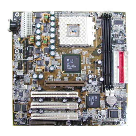
Page 8: Layout Diagram & Jumper Setting
CPU: AMD K7 900MHz/1.2GHz PGA package DRAM: 128M SDRAM x2 (Hyundai GM 72V66841ET75) VGA Expansion Card: RIVA Geforce 256 (1024x768xHi-Color) Hard Disk Driver: IBM DTLA-305040 (ATA-100) BIOS: Award Optimal default Win 98SE Performance Test Report 900MHz (100/100) 1.2GHz (133/133) 3D Mark 99 5671 5930 3D Mark 2000... - Page 9 Jumpers Jumper Name Description Page CPU Front Side Bus Frequency Setting 3-pin Block...
-
Page 10: Chapter 2 Hardware Installation
Keyboard Power ON Function Setting 3-pin Block VCC3 Voltage Setting 3-pin Block JBAT CMOS RAM Clear 3-pin Block Connectors Connector Name Description Page AT Power Connector 12-pin Block p.14 ATX Power Connector 20-pin Block p.14 ATKB Keyboard Connector 5-pin Female Connector p.15 PS2MS (J1) PS/2 Mouse Headers... -
Page 11: Hardware Installation Steps
2-1 Hardware installation Steps Before using your computer, you had better complete the following steps: 1. Check motherboard setting 2. Install CPU 3. Install Memory 4. Install Expansion cards 5. Connect Ribbon cables, Panel wires, and power supply 6. Setup BIOS 7. -
Page 12: Glossary
CMOS RAM Clear Setting (3-pin): JBAT A battery must be used to retain the motherboard configuration in CMOS RAM short 1-2 pins of JBAT to store the CMOS data. Note: You can clear CMOS by shorting 2-3 pin, while the system is unplug the power cord. -
Page 13: About Amd Athlon & Duron 462-Pin Cpu
Sound (interface) - the interface between the sound card or integrated sound connectors and speakers, mic, game controllers, and MIDI sound devices. LAN (interface) - Local Area Network - the interface to your local area network. BIOS (Basic Input/Output System) - the program logic used to boot up a computer and establish the relationship between the various components. -
Page 14: Overclock Running
When you put the CPU into the ZIF socket. No forces require to insert of the CPU, then press the level to Locate position slightly without any extra force. 2-3-3 Over clock Running WARNING! This section is for experienced motherboard installer only. Over clocking can result in system instability or even shortening life of the processor. -
Page 15: Install Memory
This item allows you to set the DRAM clock synchronous as CPU Host Clock, or Asynchronous as Host clock *4/3 to approach your SDRAM specification. 2-4 Install Memory This motherboard provides 168-pin DUAL INLINE MEMORY MODULES (DIMM) sites for memory expansion available from minimum memory size of 16MB to maximum memory size of 1GB SDRAM. -
Page 16: Procedure For Expansion Card Installation
WARNING! Turn off your power when adding or removing expansion cards or other system components. Failure to do so may cause severe damage to both your motherboard and expansion cards. 2-5-1 Procedure For Expansion Card Installation Read the documentation for your expansion card and make any necessary hardware or software setting for your expansion card such as jumpers. -
Page 17: Connectors, Headers
PCI slot 2 Shared PCI slot 3 Shared Onboard VGA AC97/MC97 Shared Onboard USB1 Shared Onboard USB 2 Shared IMPORTANT! If using PCI cards on shared slots, make sure that the drivers support “Shared IRQ”... - Page 18 * Please don’t turn off/on power supply too quickly, we recommend at least wait 4sec before turn on the power, to protect the system. 3. Keyboard Connector (5-pin female): ATKB This connection is for a standard IBM-compatible keyboard. May also be known as a 101 enhanced keyboard.
- Page 19 6. Serial port COMA and COMB Connector (Two 9-pin blocks): COM1, COM2 These connectors support the provided serial port ribbon cables with mounting bracket. Connect the ribbon cables to these connectors and mount the bracket to the case on an open slot. The two serial ports on the mounting bracket will then be used for pointing devices or other serial devices.
- Page 20 Secondary IDE Connector (40-pin block): IDE2 This connector connects to the next set of Master and Slave hard disks. Follow the same procedure described for the primary IDE connector. You may also configure two hard disks to be both, Masters using one ribbon cable on the primary IDE connector and another ribbon cable on the secondary IDE connector.
- Page 21 CD-ROM Audio connector: CD _ IN1, CD _ IN2 13. USB Port connector: USB1, USB2 14. IDE activity LED: HDLED This connector connects to the hard disk activity indicator light on the case. 15. Front Panel connector: This 16-pin connector to connect to case front panel switch.
- Page 22 This 5-pin connector connects to the case-mounted key switch for locking the keyboard for security purposes and Power LED together. 16. ATX Power button: PS/ON When using ATX power, the system power can be controlled by a momentary switch connected to PS-ON Pushing the button once will switch ON/OFF the system.
-
Page 23: Starting Up Your Computer
19. IR infrared module connector: IR This connector supports the optional wireless transmitting and receiving infrared module. This module mounts to small opening on system cases that support this feature you must also configure the setting through BIOS setup. Use the five pins as shown on the Back View and connect a ribbon cable from the module to the motherboard according to the pin definitions. -
Page 24: Chapter 3 Introducing Bios
2. Be sure all the switch are off, and check that the power supply input voltage is set to proper position, usually in-put voltage is 220V240V or 110V120V depending on your country’s voltage used. 3. Connect the power supply cord into the power supply located on the back of your system case according to your system user’s manual. -
Page 25: Entering Setup
The BIOS is a program located on a Flash Memory on the motherboard. This program is a bridge between motherboard and operating system. When you start the computer, the BIOS program gain control. The BIOS first operates an auto-diagnostic test called POST (power on self test) for all the necessary hardware, it detects the entire hardware device and configures the parameters of the hardware synchronization. -
Page 26: The Main Menu
Status Page Setup Menu/Option Page Setup Menu Press F1 to pop up a small help window that describes the appropriate keys to use and the possible selections for the highlighted item. To exit the Help Window, press <Esc>. 3-3 The Main Menu Once you enter Award ... -
Page 27: Standard Cmos Features
PnP/PCI configurations This entry appears if your system supports PnP/PCI. PC Health Status This entry shows your PC health status. Miscellaneous Control Use this menu to specify your settings for Miscellaneous control. Load Optimized Defaults Use this menu to load the BIOS default values that are factory settings for optimal performances system operations. -
Page 28: Advanced Bios Features
> IDE Primary Master Press Enter None Menu Level > > IDE Primary Slave Press Enter None > IDE Secondary Master Press Enter None Change the day, month, > IDE Secondary Slave Press Enter None year and century Drive A 1.44M, 3.25 in. - Page 29 Anti-Virus Protection Disabled Item Help PhoenixNet Support Disabled CPU L1 Cache Enabled CPU L2 Cache Enabled Menu Level > Quick Power On Self Test Enabled First Boot Device Floppy Allows you to choose Second Boot Device HDD-0 the VIRUS warning Third Boot Device CDROM feature for IDE Hard...
-
Page 30: Advanced Chipset Features
The BIOS attempts to load the operating system from the devices in the sequence selected in these items. The settings are Floppy, LS/ZIP, HDD-0/HDD-1/HDD-3, SCSI, CDROM, LAN and Disabled. Swap Floppy Drive Switches the floppy disk drives between being designated as A and B. Default is Disabled. Boot Up Floppy Seek During POST, BIOS will determine if the floppy disk drive installed is 40 or 80 tracks. - Page 31 The Advanced Chipset Features Setup option is used to change the values of the chipset registers. These registers control most of the system options in the computer. CMOS Setup Utility – Copyright(C) 1984-2001 Award Software Advanced Chipset Features > DRAM Timing Settings Press Enter Item Help >...
-
Page 32: Agp Function Settings
CMOS Setup Utility – Copyright(C) 1984-2001 Award Software DRAM Timing Setting Auto Configuration Manual Item Help RAS Active Time Auto RAS Precharg Time Auto RAS to CAS Delay Auto Menu Level >> CAS Latency Auto ↑↓→← Move Enter:Select +/-/PU/PD:Value F10:Save ESC:Exit F1:General Help F5:Previous Values F6:Optimized Defaults... -
Page 33: Integrated Peripherals
AGP Rate Auto Item Help AGP SideBand Support Disabled AGP Aperture Size 64MB AGP Aperture Size AGP Delay Offset Auto Menu Level >> ..AGP Driving Strength Auto 16MB ..32MB ..64MB ..128MB ..256MB ..:Move ENTER:Accept ESC:Abort ↑↓→←... -
Page 34: Onchip Ide Function
OnChip Device Function Please refer to section 3-7-3 Init Display First This item allows you to decide to activate whether PCI Slot or AGP VGA first. The settings are: PCI Slot, AGP Slot. Power ON Function This item allows you choose Power ON by Password, Hot KEY, Button Only, Keyboard 98 when use ATX power supply. - Page 35 IDE HDD Block Mode Block mode is also called block transfer, multiple commands, or multiple sector read/write. If your IDE hard drive supports block mode (most new drives do), select Enabled for automatic detection of the optimal number of block read/writes per sector the drive can support. The settings are: Enabled, Disabled.
-
Page 36: Power Management Setup
To operate the onboard parallel port as Standard Parallel Port only, choose “SPP.” To operate the onboard parallel port in the EPP modes simultaneously, choose “EPP.” By choosing “ECP”, the onboard parallel port will operate in ECP mode only. Choosing “ECP+EPP”... -
Page 37: Pm Wake Up Events
Power Management Setup ACPI function Enabled Item Help Video Off Option Always off Video Off Method V/H SYNC+Blank MODEM Use IRQ Menu Level > Power Button Function Instant Off > PM Wake Up Events Press Enter ↑↓→← Move Enter:Select +/-/PU/PD:Value F10:Save ESC:Exit F1:General Help F5:Previous Values F6:Optimized Defaults... -
Page 38: Pnp/Pci Configuration Setup
Wake-Up on RTC Alarm Disabled Menu Level >> x Date(of Month) Alarm x Time (hh:mm:ss) Alarm 0 : 0 : 0 > IRQs Activity Press Enter ↑↓→← Move Enter:Select +/-/PU/PD:Value F10:Save ESC:Exit F1:General Help F5:Previous Values F6:Optimized Defaults F7:Standard Defaults Wake-Up on PCI PME This will enable the system to wake up by PCI device Power Management function. -
Page 39: Irq Resources
CMOS Setup Utility – Copyright(C) 1984-2001 Award Software PnP/PCI Configurations Reset Configuration Data Disabled Item Help Resources Controlled By Manual > IRQ Resources Press Enter Menu Level > PCI/VGA Palette Snoop Disabled Default is Disabled. Assign IRQ For VGA Enabled Select Enabled to Assign IRQ For USB Enabled... -
Page 40: Pc Health Status
IRQ-5 assigned to PCI Device Menu Level >> IRQ-7 assigned to PCI Device IRQ-9 assigned to PCI Device Legacy ISA for devices IRQ-10 assigned to PCI Device Compliant with the IRQ-11 assigned to PCI Device Original PC AT bus IRQ-12 assigned to PCI Device Specification, PCI/ISA IRQ-14 assigned to... -
Page 41: Load Standard/Optimized Defaults
Spread Spectrum Disabled Menu Level > Clock Control By Hardware ** Current Host Clock is 100 MHz ** HOST clock at next boot is 100 Mhz ** Current DRAM Clock is 100 MHz ** DRAM clock at next boot is 100 Mhz (HOST CLK) ↑↓→←... -
Page 42: Set Supervisor/User Password
operations. Load Optimized Defaults When you press <Enter> on this item, you get a confirmation dialog box with a message similar to: Load Optimized Defaults (Y/N)? N Pressing <Y> loads the default values that are factory settings for optimal performance system operations. -
Page 43: Agpvxd Install Ali Vga Agpvxd Driver
detect software MAGIC INSTALL. MAGIC INSTALL supports WINDOWS 95/98/98SE/ME/NT4.0/2000 Insert CD into your CD-ROM drive and the MAGIC INSTALL Menu should appear as below. If the menu does not appear, double-click MY COMPUTER / double-click CD-ROM drive or click START / click RUN / type X:\SETUP.EXE (assuming X is your CD-ROM drive). -
Page 44: Ide Install Ali Ide Driver
For WINDOWS 98/98SE/ME/2000 Click AGPVXD when Magic Install Click Next when Install Utility appears MENU appears Click Yes to Restarting windows after You can double check in System installation finish Properties icon to make sure the AGPVXD driver already installed 4-2 IDE Install ALi IDE Driver... -
Page 45: Sound
Click IDE when Magic Install Menu Click Next to begin install ALi IDE appears driver Click Next to install ALi IDE and Cache Choose Primary/Secondary Master to Utility enable the DMA feature of IDE device and click next to install this feature Note: The path of the file is X:\ALi\M1649\IDE\SETUP.EXE 4-3 SOUND... -
Page 46: Pc-Health Install Ali Hardware Monitor Utility
Click SOUND when Magic Install Click Next to begin install ALi Audio MENU appears Driver on your computer Click Finish if you want to restart your computer after finish install the ALi Audio Driver Note: The path of the file For WIN98 is X:\ALi\M1649\Audio\Win98 For WIN95 is X:\ALi\M1649\Audio\Win95 For NT4.0 is X:\ALi\M1649\Audio\NT4... -
Page 47: Magic Bios Install Bios Live Update Utility
Click PC-Health when Magic Install Click Next to choose default destination NENU appears folder to install hardware monitor driver Click Next to add program icons to the After Install Hardware Monitor Driver Program Folder you can check in Program Folder In ALi Hardware Monitor CPU item will In System item will show System show CPU Vcore, Temperature and Fan... - Page 48 Click Magic BIOS when Magic Install Click Next to install the Magic BIOS in MENU appears Destination Folder After finish Setup you will have a Magic Double click the Magic BIOS icon you BIOS icon in your screen will have this picture, choose from internet you can upgrade BIOS On-line When On-line update BIOS the program Click Next if you need update BIOS,...
-
Page 49: Pc-Cillin Install Pc-Cillin 2000 Anti-Virus Program
Click Yes if you want to update the When System programming BIOS don’t BIOS otherwise choose No to exit turn off power, after finish update BIOS, the system will clear CMOS and automatically Restart When choose From Local Driver to 10. - Page 50 Click PC-CILLIN when MAGIC INSTALL Click NEXT when PC-CILIN 2000 SETUP MENU Appears APPEARS. Then click YES when the announcement of copywrite appears. Software is starting to detect HD for virus Click NEXT and Enter User Information, Click NEXT and Choose all Internet Click NEXT or choose BROWSE to change Protection the path For the file to be stored...
-
Page 51: How To Disable On-Board Sound Function
7. If you want to make a rescue disc, insert a 8. Setup Complete and click Finish 1.44 MB disc 9. Enter Your name and E-mail address 10. After install PC-cillin 2000 complete we Register PC-cillin 2000 or Click Cancel recommend select update item to Register Later download newest virus code and setting... -
Page 52: How To Update Bios
Copy utility program to your boot disc. You may copy from DRIVER CD X:\FLASH\AWDFLASH.EXE or download from our web site. STEP 3. Copy latest BIOS for 849BS from our web site to your boot disc. STEP 4. Insert your boot disc into A:, start the computer, type “Awdflash A:\849BSxxx.BIN /SN/PY/CC/R”...
Need help?
Do you have a question about the 849BS and is the answer not in the manual?
Questions and answers