
Related Manuals for brevini Dana E Series

Summary of Contents for brevini Dana E Series
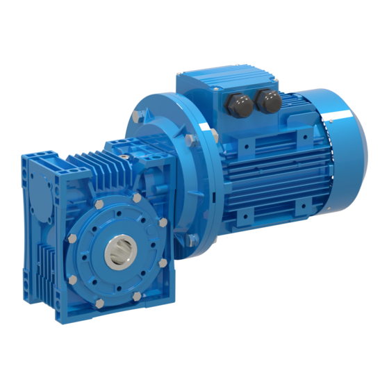
- Page 1 ® Installation and Maintenance Manual Gearmotors E Series IMM-0017EN December 2022...
- Page 2 CONTENTS DISCLAIMER The official language chosen by the Product manufacturer is English. No liability is assumed as a result of translations in other languages not in compliance with the original meaning. In case of conflicting language versions of this document, the English original prevails.
-
Page 3: Table Of Contents
CONTENTS 1 VERSION TRACKING ........................5 MANUAL APPLICABILITY AND SUPPORTED MODELS ..............5 2 HOW TO USE THIS MANUAL ......................6 3 UNIT DESIGNATION ......................... 7 DETAILED UNIT DESIGNATION ......................7 NAMEPLATE UNIT DESIGNATION ...................... 8 4 PART LIST OF STANDARD TYPE GEAR UNITS ................9 E..00 TYPES ............................ - Page 4 CONTENTS 9 MAINTENANCE & INSPECTION ....................42 10 LUBRICATION ..........................43 10.1 OIL TYPES ............................43 10.2 CHANGING THE OIL .......................... 44 10.3 MOUNTING POSITIONS ........................45 10.4 OIL QUANTITIES ..........................46 11 TROUBLESHOOTING GUIDE ......................47 12 DISPOSAL ............................50 12.1 DISPOSAL OF OIL ..........................
-
Page 5: Version Tracking
1 VERSION TRACKING File name Revision Date Changes description IMM-0017EN_Rev.00 Gearmotors E 17/10/2022 - Changed layout Series IMM-0017EN_Rev.01 Gearmotors E 07/12/2022 - Updated "Use the breather plug" page 31 Series 1.1 MANUAL APPLICABILITY AND SUPPORTED MODELS Models Gearmotors E Series IMM-0017EN - Installation and Maintenance Manual Dana Incorporated... -
Page 6: How To Use This Manual
2 HOW TO USE THIS MANUAL Take attention to the following safety and warning signs for proper understanding and quick reference. Table 1: Indicates an imminently hazardous situation which, if DANGER not avoided, will result in death or serious injury. Indicates an imminently hazardous situation which, if WARNING not avoided, could result in death or serious injury. -
Page 7: Unit Designation
3 UNIT DESIGNATION 3.1 DETAILED UNIT DESIGNATION NOTE: Detailed E series gear units designation for ordering (This Designation is different from the short nameplate designation) E V 063 . 01 - 90S/4 - L05 Brake 01 -10 Nm 10 -100Nm 02 -25 Nm 20 -200 Nm 04 -40 Nm... -
Page 8: Nameplate Unit Designation
UNIT DESIGNATION 3.2 NAMEPLATE UNIT DESIGNATION NOTE: Nameplate unit designation is a short abbreviation from the detailed designation. A sample name plate for E Series Type EV080.00-90S/4 100536041 Serial N.: MADE IN TURKEY Power : Ratio: Speed rpm. M. Pos.: ISO VG320 Oil Qty : (Synthetic Oil) -
Page 9: Part List Of Standard Type Gear Units
4 PART LIST OF STANDARD TYPE GEAR UNITS 4.1 E..00 TYPES IMPORTANT: Standard E...00... type basic part diagram. Parts may differ for special applications. Standard Part List Standard Part List Standard Part List Housing Bearing Oil Seal Closing Cap O-Ring Bolt Circlips Input Flange... -
Page 10: Types
PART LIST OF STANDARD TYPE GEAR UNITS 4.2 E..01 TYPES IMPORTANT: Standard E...01... type basic part diagram. Parts may differ for special applications. Standard Part List Standard Part List Standard Part List Bearing Worm Gear Housing Bearing Solid Output Shaft Closing Cap O-ring Seal... -
Page 11: Types
PART LIST OF STANDARD TYPE GEAR UNITS 4.3 E..02 TYPES IMPORTANT: Standard E...02... type basic part diagram. Parts may differ for special applications. Standard Part List Standard Part List Standard Part List Bearing Seal Worm Wheel Oil Plug Solid Output Shaft Bearing Worm Gear Bolt... -
Page 12: Types
PART LIST OF STANDARD TYPE GEAR UNITS 4.4 E..03 TYPES IMPORTANT: Standard E...03... type basic part diagram. Parts may differ for special applications. Standard Part List Standard Part List Standard Part List Worm Wheel Oil Plug Bolt Bearing Worm Gear Flange Housing Bearing... -
Page 13: Types
PART LIST OF STANDARD TYPE GEAR UNITS 4.5 E...04 TYPES IMPORTANT: Standard E...04... type basic part diagram. Parts may differ for special applications. Standard Part List Standard Part List Bearing Circlips Solid Output Shaft Washer Seal Seal Bolt Oil Plug Side Cover Worm Gear O-Ring... -
Page 14: Types
PART LIST OF STANDARD TYPE GEAR UNITS 4.6 E..05 TYPES IMPORTANT: Standard E...05... type basic part diagram. Parts may differ for special applications. Standard Part List Standard Part List Closing Cap Circlips Solid Output Shaft Bearing Circlips Circlips Bolt Seal Flange Oil Plug O-Ring... -
Page 15: Types
PART LIST OF STANDARD TYPE GEAR UNITS 4.7 E..08 TYPES IMPORTANT: Standard E...08... type basic part diagram. Parts may differ for special applications. Standard Part List Standard Part List Standard Part List Worm Wheel Oil Plug Bolt Bearing Worm Gear Output Flange Housing Bearing... - Page 16 PART LIST OF STANDARD TYPE GEAR UNITS 4.8 ET...00 TYPES IMPORTANT: Standard ET...00... type basic part diagram. Parts may differ for special applications. Standard Part List Standard Part List Standard Part List Housing Seal Closing Cap Bearing Bolt Circlips O-Ring Side Cover Bearing Flange...
- Page 17 PART LIST OF STANDARD TYPE GEAR UNITS 4.9 ET...01 TYPES IMPORTANT: Standard ET..01... type basic part diagram. Parts may differ for special applications. Standard Part List Standard Part List Standard Part List Bearing Worm Gear Housing Solid Output Shaft Closing Cap Bearing Seal Circlips...
- Page 18 PART LIST OF STANDARD TYPE GEAR UNITS 4.10 ET...02 TYPES IMPORTANT: Standard ET..02... type basic part diagram. Parts may differ for special applications. Standard Part List Standard Part List Standard Part List Worm Wheel Worm Gear Bearing Solid Output Shaft Housing Bearing Bolt...
- Page 19 PART LIST OF STANDARD TYPE GEAR UNITS 4.11 ET..03 TYPES IMPORTANT: Standard ET...03... type basic part diagram. Parts may differ for special applications. Standard Part List Standard Part List Standard Part List Bearing Bolt Housing Bearing Flange Closing Cap O-Ring Seal Circlips Motor Flange...
- Page 20 PART LIST OF STANDARD TYPE GEAR UNITS 4.12 ET...04 TYPES IMPORTANT: Standard ET...04... type basic part diagram. Parts may differ for special applications. Standard Part List Standard Part List Standard Part List Housing Closing Cap Bearing Solid Output Shaft Circlips O-Ring Seal Bearing...
- Page 21 PART LIST OF STANDARD TYPE GEAR UNITS 4.13 ET...05 TYPES IMPORTANT: Standard ET...05... type basic part diagram. Parts may differ for special applications. Standard Part List Standard Part List Closing Cap Circlips Solid Output Shaft Bearing Circlips Circlips Bolt Seal Output Flange Oil Plug Seal...
- Page 22 PART LIST OF STANDARD TYPE GEAR UNITS 4.14 ET..08 TYPES IMPORTANT: Standard ET...08... type basic part diagram. Parts may differ for special applications. Standard Part List Standard Part List Standard Part List Bearing Bolt Housing Bearing Output Flange Closing Cap O-Ring Seal Circlips...
-
Page 23: Safety
5 SAFETY 5.1 INTENDED USE The gear reducer is designed for use in industrial machines. Please refer to our catalogue or our web page for the maximum permitted torques and speeds. The most important maximum permitted values are indicated on the nameplate of the product. But the whole data can be found on our product catalogues. -
Page 24: Safety Instructions
SAFETY 5.3 SAFETY INSTRUCTIONS 5.3.1 GENERAL SAFETY INSTRUCTIONS 5.3.1.1 Working on the gear reducer WARNING Inappropriately executed work can lead to injury or damage. Make sure that the gear reducer is only installed, maintained and dismantled by trained technicians. WARNING Foreign bodies spinning through the air can cause grave injury. - Page 25 SAFETY 5.3.1.4 Lubricant WARNING Extended, intensive contact with oils can lead to skin irritations. Avoid extended contact with oil, and clean oil off skin thoroughly. WARNING Hot oil can cause scalding. When changing oil, protect yourself against contacting hot oil. 5.3.1.5 Ambient Conditions DANGER If the gear unit will be used in outdoor applications the gear unit must be prevented from rain snow and dust.
-
Page 26: Tightening Torques
SAFETY 5.4 TIGHTENING TORQUES All screwed connections for which a tightening torque is specified, must on principle be tightened with a calibrated torque wrench and checked. Use the following torques for the threaded bores over the gear unit housing. For connecting elements refer to the mechanical installation part. -
Page 27: Thinks To Check Before The Gear Unit Or Geared Motor Is Installed
6 THINKS TO CHECK BEFORE THE GEAR UNIT OR GEARED MOTOR IS INSTAL- NOTE: If geared motors are used, please also refer to the manual of the motor manufacturer. Before you install the gearbox you have to be sure that the gearbox is arrived with the all necessary equipment and without damage. -
Page 28: Installing The Gear Unit
7 INSTALLING THE GEAR UNIT 7.1 BEFORE YOU START • Observe the gear unit for damages of storage or transportation. If any damage please contact Dana Motion Systems Italia S.r.l.. • Be sure that you have all the equipment necessary for installing like; Spanners, torque wrench, shims and distance rings, fixing devices for input and output elements, lubricant, bolt adhesive etc. -
Page 29: Check The Voltage Supply
INSTALLING THE GEAR UNIT 7.4 CHECK THE VOLTAGE SUPPLY The standard geared motors are supplied with 230/400 V 50/60 Hz up to 3 kW including 3 kW and 400/690 V 50/60 Hz over 3 kW and is indicated on the motors name plate unless it is differently ordered. In case of only gear unit is supplied from Dana Motion Systems Italia S.r.l. - Page 30 INSTALLING THE GEAR UNIT Standard type brakes basic wiring diagram DANGER The electric connection must be done by experienced electric technician. The gearbox and the motor must be grounded to prevent potential differences of earth and gearbox/motor. Delayed Running Brake ( 220 V) Sudden Brake (220 V) R S T R S T N...
-
Page 31: Check The Mounting Position
INSTALLING THE GEAR UNIT 7.5 CHECK THE MOUNTING POSITION The mounting position must be in accordance with the mounting position mentioned on the name plate. If different please con- tact Dana Motion Systems Italia S.r.l. for possibilities of using in a different mounting position. Refer to the mounting positions and oil quantities on this manual and adjust the oil level accordingly with the recommended oil types given on this manuel. -
Page 32: Cover Abrasive Ambient
INSTALLING THE GEAR UNIT 7.9 COVER ABRASIVE AMBIENT If the gear unit will be placed on a abrasive ambient be sure that the output seals are covered so that no abrasive material, chemicals or water touches the seals. Any pressure coming from outside over the seals can cause that the out staying sub- stances to enter the gearbox and cause serious damage to the gear unit. -
Page 33: Mechanical Installation
8 MECHANICAL INSTALLATION The gear unit can only be installed using the supplied connection points like foot and flange assembling points. DANGER To install the gear unit without the supplied connection points can cause serious injuries by loosening or braking the gear unit. Even the gear unit is installed totally correctly according this manual, be sure that no one will be harmed by accidentally brake downs or loosening. -
Page 34: Installing Customer Shaft With Shoulder
MECHANICAL INSTALLATION 8.1 INSTALLING CUSTOMER SHAFT WITH SHOULDER Use anti-seize assembling paste available on your market. Use a brush to apply the paste. Fasten the bold as shown below. Retaining Bolt Lock Washer Washer Circlips Hollow Shaft Customer Shaft Dana Incorporated IMM-0017EN - Installation and Maintenance Manual... -
Page 35: Shaft Tightening Torques
MECHANICAL INSTALLATION 8.2 SHAFT TIGHTENING TORQUES Use the following table for shaft tightening torques. Type Bolt Tightining Torque [Nm] E.030 E.040 E.050 E.063 E.075 E.080 E.100 E.125 IMM-0017EN - Installation and Maintenance Manual Dana Incorporated... -
Page 36: Advised Shaft Dimensions And Accessiories
MECHANICAL INSTALLATION 8.3 ADVISED SHAFT DIMENSIONS AND ACCESSIORIES Advised shaft dimensions are indicated below and YILMAZ REDUKTOR provides this dimensions as standart. Table 6: Mounting Dimensions Weight Type E.030.. 51,5 120.5 0.18 0.20 0.35 0.27 0.15 E.040.. 44,5 151.5 20.5 0.35 0.30 0.55... -
Page 37: Torque Arm Connection
MECHANICAL INSTALLATION 8.4 TORQUE ARM CONNECTION Use the torque arm connection according the following drawing. IMM-0017EN - Installation and Maintenance Manual Dana Incorporated... - Page 38 MECHANICAL INSTALLATION Assemble the parts as shown bellow Bolt Washer Bolt Torque arm Machine Connection Arm Dana Incorporated IMM-0017EN - Installation and Maintenance Manual...
- Page 39 MECHANICAL INSTALLATION For the fixing bold position refer to the following dimensions Table 7: Type Part No E.030.. 9E030 E.040.. 9E040 E.050.. 9E050 E.063.. 49,5 9E063 E.075.. 49,5 9E075 E.080.. 49,5 9E080 E.100.. 57,5 9E100 E.125.. 9E125 IMM-0017EN - Installation and Maintenance Manual Dana Incorporated...
-
Page 40: Fitting Outputshaft Elements
MECHANICAL INSTALLATION 8.5 FITTING OUTPUTSHAFT ELEMENTS Use the following illustration to assemble output shaft units Gear shaft end Thrust bearing Coupling hub 8.6 CORRECT POSITION OF OUTPUT SHAFT ELEMENTS The Output Shaft unit (transmission elements) must placed as close as possible to the gear unit so that the radial load is as closest as possible to the gear unit. -
Page 41: Fitting Couplings
MECHANICAL INSTALLATION 8.7 FITTING COUPLINGS By fitting couplings be sure that there is some clearance between the two elements By fitting couplings be sure that there is no eccentric between the two shafts. By fitting couplings be sure that the two shafts are not angular miss-aligned. IMM-0017EN - Installation and Maintenance Manual Dana Incorporated... -
Page 42: Maintenance & Inspection
9 MAINTENANCE & INSPECTION Under normal ambient and working conditions the gear unit should be checked according the following intervals. (For definition of normal working conditions refer to the product catalogue: “Selecting Gearbox” section); Table 8: Every 3.000 working hours Every 10.000 working Every 25.000 working Item to check /replace... -
Page 43: Lubrication
10 LUBRICATION 10.1 OIL TYPES Table 9: Beyond Klüber Ambient Temperature Aral Petro- Castrol Lubrica- Mobil Shell Total [ºC] leum tion Lubricant ISO VG 51517-3 Forced Dip Lubri- Lubrica- cation tion Klüberoil Degol BG Energol Alpha SP Mobilgear Carter EP 0 ... -
Page 44: Changing The Oil
LUBRICATION Beyond Klüber Ambient Temperature Aral Petro- Castrol Lubrica- Mobil Shell Total [ºC] leum tion Lubricant ISO VG 51517-3 Forced Dip Lubri- Lubrica- cation tion Cassida Food CLP NSF Optileb GT Klüberoil 4 Mobil SHC Nevastane -15 ... +25 +5 ... +25 –... -
Page 45: Mounting Positions
LUBRICATION 10.3 MOUNTING POSITIONS Figured mounting positions of M1 to M6 are determined as reference of directional position of the gearbox. Mounting surfaces are not binding. IMM-0017EN - Installation and Maintenance Manual Dana Incorporated... -
Page 46: Oil Quantities
LUBRICATION 10.4 OIL QUANTITIES Oil Quantities Table 10: Type E.30 0,025 0,04 0,02 0,04 0,04 0,04 E.40 0,07 0,10 0,12 0,10 0,10 0,10 E.50 0,15 0,15 0,15 0,15 0,15 0,15 E.63 0,30 0,40 0,25 0,40 0,40 0,40 E.75 0,45 0,60 0,40 0,65 0,65... -
Page 47: Troubleshooting Guide
11 TROUBLESHOOTING GUIDE WARNING All the operations bellow must be done by authorized and skilled mechanician/electrician. Inform Dana Motion Systems Italia S.r.l. before making any change to the gearbox. Only oil change is allowed to change with- out information. Do not make any think if you are not sure what you are doing and contact Dana Motion Systems Italia S.r.l.. Any change or operation done without the information of Dana Motion Systems Italia S.r.l. - Page 48 TROUBLESHOOTING GUIDE Problem Observation Remedy Measure the surface temp. using a temperature measuring de- vice under full load. If the temp is under +80 Celsius this will make no harm to the gearbox and is normal. All ATEX conforming gear- boxes and standart worm gearboxes are designed to work under You are using Worm Gear Box max.
- Page 49 TROUBLESHOOTING GUIDE Problem Observation Remedy Observe exactly where the oil is comming out. It could be seal or plug point where it comes out and leakes over the housing. If this Oil is Leaking Oil Leakage from Housing is your case goto ID 018/019. If you are sure oil comes out from housing than housing has some micro split / crack.
-
Page 50: Disposal
12 DISPOSAL If your product is no longer of use and you wish to dispose of it, refer to the instructions here. If you have any questions regarding ecological disposal methods, please consult our service points given on the backside of this manuel. 12.1 DISPOSAL OF OIL Lubricants (oil and greases) are hazardous substances, which can contaminate soil and water. - Page 51 IMM-0017EN - Installation and Maintenance Manual Dana Incorporated...
- Page 52 Copyright 2022 Dana Incorporated For product inquiries or support, All content is subject to copyright by Dana and may not visit www.dana.com. be reproduced in whole or in part by any means, ® For other service publications, visit electronic or otherwise, without prior written approval. www.danaaftermarket.com/literature-library THIS INFORMATION IS NOT INTENDED FOR SALE OR For online service parts ordering,...