Table of Contents
Advertisement
Quick Links
Instruction manual
EV-100
Damper Interface Control Panel
SCS BA EV-100 EN 1.0
The supplementary sheet "Safety instructions and Warranty conditions" contains general
and product-specific warnings and the intended use.
This document is invalid without the supplement!
groupscs.co.uk
SCS_BA_EV-100_EN_10
Date: 21.11.2022
Issue: 1.0 / 1 1.2022
info@groupscs.co.uk
Valid for firmware S1.0.0.12
Advertisement
Table of Contents

Related Manuals for GROUP SCS EV-100

Summary of Contents for GROUP SCS EV-100
- Page 1 Instruction manual EV-100 Damper Interface Control Panel SCS BA EV-100 EN 1.0 The supplementary sheet “Safety instructions and Warranty conditions” contains general and product-specific warnings and the intended use. This document is invalid without the supplement! groupscs.co.uk SCS_BA_EV-100_EN_10 Date: 21.11.2022 Issue: 1.0 ...
-
Page 2: Table Of Contents
Technical information ..........................6 2.1. Power supply information ..........................6 2.2. Actuator output ............................6 2.3. 230V Module (EV-100-OB) Output ......................6 2.4. Indications (Feedback) ..........................6 2.5. FAS input for smoke detector EV-SD ......................6 2.6. Mechanical features ............................ 6 2.7. - Page 3 Contents Appendix ..............................14 8.1. Manufacturer‘s declaration EC ........................14 8.2. EC manufacturer‘s declaration ( distributor) ....................14 8.3. Manufacturer‘s declaration UK ........................14 8.4. UK manufacturer‘s declaration ( distributor) ....................14 8.5. Company address ............................. 14 SCS_BA_EV-100_EN_10 groupscs.co.uk Date: 21.11.2022 Issue: 1.0 ...
-
Page 4: Dimensions
Dimensions Dimensions 1.1. EV-100 Interface panel 1.2. EV-100 Hot box SCS_BA_EV-100_EN_10 groupscs.co.uk Date: 21.11.2022 info@groupscs.co.uk Issue: 1.0 / 1 1.2022 Page 4... -
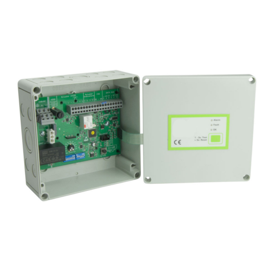
Page 5: Ev-100 Internal Arrangement
Dimensions 1.3. EV-100 Internal arrangement Terminations Mains terminal Fuses 230 V AC supply for EV-100-OB Addressing SW1 Reset Button Rotary switch for damper position Status Indication Configuration SW2 SCS_BA_EV-100_EN_10 groupscs.co.uk Date: 21.11.2022 Issue: 1.0 / 1 1.2022 info@groupscs.co.uk Page 5... -
Page 6: Technical Information
0.5 mm² - 2.5 mm² 2014 / 3 0 / E U and the low voltage directive 2.3. 230V Module (EV-100-OB) Output 2014 / 3 5 / E U UK compliant As per Electromagnetic Output voltage (mains nominal) -
Page 7: Product Description
The status of the panel is indicated by coloured LEDs located 3.1. Functional specifications on the control board and the front panel mimic. The EV-100 functions as a fire damper and smoke control 3.5.1. Control board indicators damper interface panel. The panel provides a power supply... -
Page 8: Configuration Switches
General Functions 3.7. Configuration switches 4.4. Lockout Lockout only applies when in a network configuration. Con- Function nection to the master panel is monitored and when a discon- nection is detected the panel activates lockout mode. 2..10V 0..10V Modulating position feedback range Only applicable when SW2-5 is set to If the panel was in normal mode when lockout is activated modulating. -
Page 9: Installation Instructions
Installation Instructions Installation Instructions DANGER Risk of electrocution. Works on this equipment should only be carried out by a qualified and competent electrical person. Observe all electrical safety regulations and safe systems of work. Check power supply has been isolated or disconnected safely before removing equipment covers. -
Page 10: Addressable Damper System - Smoke Control Dampers (Failsafe In Position)
Installation Instructions 5.2. Addressable Damper System – Smoke Control Dampers (Failsafe in Position) 24 V Smoke Control Damper 230 V Smoke Control Damper Fail in Position (Non-Spring) Fail in Position (Non-Spring) 230 V Smoke Control Damper Fail in Position (Non-Spring) SCS_BA_EV-100_EN_10 groupscs.co.uk Date: 21.11.2022... -
Page 11: Standalone Damper Control - Fire & Smoke Dampers (Spring Close)
Installation Instructions 5.3. Standalone Damper Control – Fire & Smoke Dampers (Spring Close) 24 V Fire Damper Spring Close 230 V Fire Damper Spring Close 24 V Modulating Fire Damper Spring Close SCS_BA_EV-100_EN_10 groupscs.co.uk Date: 21.11.2022 Issue: 1.0 / 1 1.2022 info@groupscs.co.uk Page 11... -
Page 12: Standalone Damper Control - Smoke Control Dampers (Failsafe In Position)
Installation Instructions 5.4. Standalone Damper Control – Smoke Control Dampers (Failsafe in Position) 24 V Smoke Control Damper 230 V Smoke Control Damper Fail in Position (Non-Spring) Fail in Position (Non-Spring) 230 V Smoke Control Damper Fail in Position (Non-Spring) SCS_BA_EV-100_EN_10 groupscs.co.uk Date: 21.11.2022... -
Page 13: Commissioning Instructions
The control board is sensitive to electrostatic discharge causing damage to components. Do not remove or handle ¾ Set the EV-100 panel address (switch SW1) starting from the board, this may invalidate the warranty. 1 up to 60 for each network (see section 3.6). -
Page 14: Troubleshooting
= 20 MΩ/km (wire manu- facturer specification), otherwise disconnections may be undetected. INFORMATION The EV-100 indications are only visible with mains power connected. For more information about the operational status see 3.5.1.: “Control board indicators” on page 7.
Need help?
Do you have a question about the EV-100 and is the answer not in the manual?
Questions and answers