Table of Contents
Advertisement
Quick Links
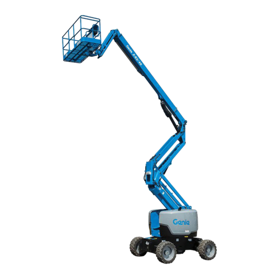
Operator's Manual
Z
-62/40
®
Serial Number Range
from Z6215A-101 to Z6216A-1086
from Z6216N-1087 to Z6216N-2999
from Z6216D-101 to Z6216D-136
from Z6216M-101 to Z6216M-399
from Z62M-400 to 1500
from Z62D-150
from Z62H-3000
CE
with
Maintenance
Information
Original Instructions
First Edition
Third Printing
Part No. 1257653GT
Advertisement
Table of Contents

Related Manuals for Terex Genie Z6216D-101


Summary of Contents for Terex Genie Z6216D-101
- Page 1 Operator's Manual Serial Number Range -62/40 ® from Z6215A-101 to Z6216A-1086 from Z6216N-1087 to Z6216N-2999 from Z6216D-101 to Z6216D-136 from Z6216M-101 to Z6216M-399 from Z62M-400 to 1500 from Z62D-150 from Z62H-3000 with Maintenance Information Original Instructions First Edition Third Printing Part No.
-
Page 2: Table Of Contents
NG31 6BH Copyright © 2014 Terex Corporation First Edition: Third Printing, December 2022 Genie and "Z" are registered trademarks of Terex South Dakota, Inc. in the U.S.A. and many other countries. Complies with EC Directive 2006/42/EC See EC Declaration of Conformity Supply of Machinery (Safety) Regulations 2008 ®... -
Page 3: Introduction
First Edition • Third Printing Operator's Manual Introduction Introduction About this manual Intended Use and Familiarization Guide Genie appreciates your choice of our machine for your application. Our number one priority is user The intended use of this machine is to lift safety, which is best achieved by our joint efforts. - Page 4 Operator's Manual First Edition • Third Printing Introduction Platform controls symbology and related Ground controls symbology and related machine movement: machine movement: Platform level swtich Platform level, jib boom up/down, primary boom extend/retract, primary boom up/down, and secondary boom Platform rotate switch retract/lower.
- Page 5 First Edition • Third Printing Operator's Manual Introduction Bulletin Distribution and Contacting the Manufacturer Compliance At times it may be necessary to contact Genie. When you do, be ready to supply the model Safety of product users is of paramount number and serial number of your machine, along importance to Genie.
- Page 6 Operator's Manual First Edition • Third Printing Introduction Safety Sign Maintenance Replace any missing or damaged safety signs. Keep operator safety in mind at all times. Use mild soap and water to clean safety signs. Do not use solvent-based cleaners because they may damage the safety sign material.
-
Page 7: Symbol And Hazard Pictorials Definitions
First Edition • Third Printing Operator's Manual Symbol and Hazard Pictorials Definitions Symbol and Hazard Pictorials Definitions Fire hazard Explosion hazard Explosion hazard Do not use ether or No smoking. other high energy No flame. starting aids on Stop engine. machines equipped with glow plugs. - Page 8 Operator's Manual First Edition • Third Printing Symbol and Hazard Pictorials Definitions Tie-down point Lifting point Platform tie-down Lifting and tie down Lanyard anchorage instructions instructions points Color coded direction Corrosive acid. Runaway hazard Collision hazard Overhead obstruction arrows Electrocution hazard Avoid contact Disconnect battery Voltage rating for...
- Page 9 First Edition • Third Printing Operator's Manual Symbol and Hazard Pictorials Definitions Recovery procedure if tilt alarm sounds while elevated. Platform uphill: Platform downhill: Read the operator’s Read the service Access by trained manual manual and authorized 1 Lower primary. 1 Retract primary.
-
Page 10: General Safety
Operator's Manual First Edition • Third Printing General Safety General Safety ® -62/40 Part No. 1257653GT... - Page 11 First Edition • Third Printing Operator's Manual General Safety ® Part No. 1257653GT -62/40...
- Page 12 Operator's Manual First Edition • Third Printing General Safety ® -62/40 Part No. 1257653GT...
-
Page 13: Personal Safety
First Edition • Third Printing Operator's Manual Personal Safety Personal Safety Personal Fall Protection Personal fall protection equipment (PFPE) is required when operating this machine. Occupants must wear a safety belt or harness in accordance with governmental regulations. Attach the lanyard to the anchor provided in the platform. Operators must comply with employer, job site and governmental rules regarding the use of personal protective equipment. -
Page 14: Work Area Safety
Operator's Manual First Edition • Third Printing Work Area Safety Work Area Safety Electrocution Hazards Keep away from the machine if it contacts This machine is not electrically insulated and will energized power lines. not provide protection from contact with or Personnel on the ground or proximity to electrical current. - Page 15 First Edition • Third Printing Operator's Manual Work Area Safety Do not raise or extend the If the tilt alarm sounds boom unless the machine with the platform uphill: is on a firm, level surface. Lower the primary boom. Lower the secondary boom.
- Page 16 Operator's Manual First Edition • Third Printing Work Area Safety Do not alter or disable machine components that Use extreme care and in any way affect safety and stability. slow speeds while driving the machine in the stowed Do not replace items critical to machine stability position across uneven with items of different weight or specification.
- Page 17 First Edition • Third Printing Operator's Manual Work Area Safety Operation on Slopes Hazards Do not place or attach fixed or overhanging loads Do not drive the machine on a slope that exceeds to any part of this the maximum uphill, downhill or side slope rating machine.
- Page 18 Operator's Manual First Edition • Third Printing Work Area Safety Fall Hazards Collision Hazards Occupants must wear a Be aware of limited sight safety belt or harness in distance and blind spots accordance with when driving or operating. governmental regulations. Attach the lanyard to the anchor provided in the Be aware of the boom position and tailswing when...
- Page 19 First Edition • Third Printing Operator's Manual Work Area Safety Bodily Injury Hazard Observe and use the color-coded direction arrows on the platform controls and drive chassis for drive Always operate the machine in a well-ventilated and steer functions. area to avoid carbon monoxide poisoning. Do not lower the boom Do not operate the machine with a hydraulic oil or unless the area below is...
- Page 20 Operator's Manual First Edition • Third Printing Work Area Safety Damaged Machine Hazards Battery Safety Do not use a damaged or malfunctioning machine. Burn Hazards Conduct a thorough pre-operation inspection of Batteries contain acid. the machine and test all functions before each Always wear protective work shift.
- Page 21 First Edition • Third Printing Operator's Manual Work Area Safety Panel Cradle Safety Pipe Cradle Safety Read, understand and obey all warnings and Read, understand, and obey all warnings and instructions provided with the panel cradles. instructions provided with the pipe cradles. Do not exceed the rated platform capacity.
- Page 22 Operator's Manual First Edition • Third Printing Work Area Safety Welder Safety Tow Package Safety Read, understand and obey all warnings and Read, understand and obey all warnings and instructions provided with the welding power unit. instructions provided with the tow package. Do not connect weld leads or cables unless the When vehicle is in free-wheel configuration, there welding power unit is turned off at the platform...
- Page 23 First Edition • Third Printing Operator's Manual Work Area Safety Lockout After Each Use Select a safe parking location—firm level surface, clear of obstruction and traffic. Retract and lower the boom to the stowed position. Rotate the turntable so that the boom is between the non-steer wheels.
-
Page 24: Legend
Operator's Manual First Edition • Third Printing Legend Legend Pictures in this manual may show a boom with tires and wheels instead of tracks. All safety information and operating instructions still apply to the Z-62/40 TRAX, even if the picture does not show the tracks. Foot switch Ground controls Manual storage container... -
Page 25: Controls
First Edition • Third Printing Operator's Manual Controls Controls The ground control station is to be used as a means to raise the platform for storage purposes and for function tests. The ground control station can be used in the event of an emergency to rescue an incapacitated person in the platform. - Page 26 Operator's Manual First Edition • Third Printing Controls Ground Control Panel Gasoline/LPG models: Check engine light Diesel models: Oil pressure light Function enable button Light on and engine stopped: Tag the machine Press and hold the function enable button to and remove from service.
- Page 27 First Edition • Third Printing Operator's Manual Controls 11 Gasoline/LPG models: Fuel select switch 15 Engine start switch Move the fuel select switch to the gasoline Move the engine start switch to either side to position to select gasoline. Move the fuel start the engine.
- Page 28 Operator's Manual First Edition • Third Printing Controls Platform Control Panel Horn button Platform control box heater (if equipped) Platform level switch 10 Generator switch (if equipped) Platform rotate switch 11 Aircraft protection override switch (if equipped) Jib boom up/down switch 12 Steer mode select switch (if equipped) Platform overload indicator light 13 Red Emergency Stop button...
- Page 29 First Edition • Third Printing Operator's Manual Controls 15 Drive enable indicator light 20 Gasoline/LPG models: Fuel select switch 16 Drive enable switch 21 Proportional control handle for secondary boom up/down function 17 Diesel models:Glow plug switch 22 Primary boom extend/retract switch 18 Engine idle (rpm) select switch 23 Dual axis proportional control handle for primary Turtle: foot switch activated low idle...
- Page 30 Operator's Manual First Edition • Third Printing Controls Platform Control Panel Machine not level indicator light The machine not level indicator light will come Horn button on when the tilt alarm sounds. Press this button and the horn will sound. Auxiliary power switch with cover Release the button and the horn will stop.
- Page 31 First Edition • Third Printing Operator's Manual Controls 13 Red Emergency Stop button 15 Drive enable indicator light Push in the red Emergency Stop button to the Light on indicates that the boom has moved off position to stop all functions and turn the just past either non-steer wheel and drive engine off.
- Page 32 Operator's Manual First Edition • Third Printing Controls 21 Proportional control handle for secondary boom up/down function Move the control handle up and the secondary boom will raise. Move the control handle down and the secondary boom will lower. 22 Primary boom extend/retract switch Move the primary boom extend/retract switch up and the primary boom will...
-
Page 33: Inspections
First Edition • Third Printing Operator's Manual Inspections Inspections Pre-operation Inspection Fundamentals It is the responsibility of the operator to perform a pre-operation inspection and routine maintenance. The pre-operation inspection is a visual inspection performed by the operator prior to each work shift. Do Not Operate Unless: The inspection is designed to discover if anything is apparently wrong with a machine before the... - Page 34 Operator's Manual First Edition • Third Printing Inspections Pre-operation Inspection ❑ Engine and related components ❑ Limit switches and horn ❑ Be sure that the operator’s manual is ❑ Contact alarm (if equipped) complete, legible and in the storage container located in the platform.
- Page 35 First Edition • Third Printing Operator's Manual Inspections Function Test Fundamentals The function tests are designed to discover any malfunctions before the machine is put into service. The operator must follow the step-by-step instructions to test all machine functions. A malfunctioning machine must never be used. If Do Not Operate Unless: malfunctions are discovered, the machine must be tagged and removed from service.
- Page 36 Operator's Manual First Edition • Third Printing Inspections At the Ground Controls Test the Tilt Sensor Turn the key switch to Select a test area that is firm, level and free of platform control. Pull out the hazards. platform red Emergency Turn the key switch to ground control.
- Page 37 First Edition • Third Printing Operator's Manual Inspections At the Platform Controls Test Machine Functions 24 Press down the foot switch. Test Emergency Stop 25 Activate each machine function control handle 15 Turn the key switch to platform control and or toggle switch.
- Page 38 Operator's Manual First Edition • Third Printing Inspections Models with 4 wheel steer 34 Slowly move the control handle in the direction indicated by the yellow triangle on the control Test the Steering panel OR press the thumb rocker switch in the direction indicated by the yellow triangle.
- Page 39 First Edition • Third Printing Operator's Manual Inspections Test the Drive Enable System Test Limited Drive Speed 39 Press down the foot switch and lower the 43 Press down the foot switch. boom to the stowed position. 44 Raise the primary boom approximately 61 cm. 40 Rotate the turntable until the primary boom 45 Slowly move the drive control handle to the full moves past one of the non-steer or circle-end...
- Page 40 Operator's Manual First Edition • Third Printing Inspections Test Drive Tilt Cutout 61 Return to level ground and stow the boom. 53 Press down the foot switch. 62 With the boom fully stowed, drive the machine onto a slope where the chassis pitch angle is 54 With the boom fully stowed, drive the machine greater than 4.5°.
- Page 41 First Edition • Third Printing Operator's Manual Inspections Test the Oscillating Axle (if equipped) 69 Return to level ground and extend the primary boom approximately 1.6 ft / 0.5 m. 77 Start the engine from the platform controls. 70 Drive the machine onto a slope where the 78 Drive the right steer tire up onto a 15 cm block chassis roll angle is greater than 2.5°.
- Page 42 Operator's Manual First Edition • Third Printing Inspections Test the Contact Alarm (if equipped) 90 Operate each machine function. 86 Do not activate the foot switch and press on Result: All machine functions should not the contact alarm cable to release the actuator operate.
- Page 43 First Edition • Third Printing Operator's Manual Inspections Test the Lift/Drive Select Function Test Aircraft Protection Package (if equipped) 93 Press down the foot switch. Note: Two people may be required to perform this 94 Move the drive control handle off center and test.
- Page 44 Operator's Manual First Edition • Third Printing Inspections Workplace Inspection Checklist Be aware of and avoid the following hazardous situations: ❑ drop-offs or holes ❑ bumps, floor obstructions, or debris ❑ sloped surfaces Do Not Operate Unless: ❑ unstable or slippery surfaces ...
- Page 45 First Edition • Third Printing Operator's Manual Inspections Decal Inspection Part No.Decal Description 133067 Label – Electrocution Hazard Use the pictures on the next page to verify that all 133205 Label – Electrocution/Burn Hazard decals are legible and in place. 133263 Label –...
- Page 46 Operator's Manual First Edition • Third Printing Inspections 1253845 **114236 *28160 114252 ***82487 114252 72086 ***82487 133067 82487 114251 *1298991 1257660 82481 114248 219956 219958 *28160 133205 *28158 1263542 *28159 219954 114252 *1301030 1257661 27207 27206 27204 114252 27206 *44981 27207 **72086 27205...
-
Page 47: Operating Instructions
First Edition • Third Printing Operator's Manual Operating Instructions Operating Instructions Fundamentals The Operating Instructions section provides instructions for each aspect of machine operation. It is the operator’s responsibility to follow all the safety rules and instructions in the operator’s manual. - Page 48 Operator's Manual First Edition • Third Printing Operating Instructions Starting the Engine All models If the engine fails to start after 15 seconds of At the ground controls, turn the key switch to cranking, determine the cause and repair any the desired position.
- Page 49 First Edition • Third Printing Operator's Manual Operating Instructions Emergency Stop Operation from Ground Push in the red Emergency Stop button to the off Turn the key switch to ground control. position at the ground controls or the platform Pull out the red Emergency Stop button to the controls to stop all machine functions and turn the on position.
- Page 50 Operator's Manual First Edition • Third Printing Operating Instructions Operation from Platform To Drive Press down the foot switch. Turn the key switch to platform control. Increase speed: Slowly move the control Pull out both ground and platform red handle off center. Emergency Stop buttons to the on position.
- Page 51 First Edition • Third Printing Operator's Manual Operating Instructions Driving on a slope To determine the slope grade: Determine the uphill, downhill and side slope Measure the slope with a digital inclinometer OR ratings for the machine and determine the slope use the following procedure.
- Page 52 Operator's Manual First Edition • Third Printing Operating Instructions Drive Enable Engine Idle Select (rpm) When the foot switch is not pressed, the engine Light on indicates that the boom will idle at the lowest rpm. has moved just past either non- steer or circle-end wheel and the •...
- Page 53 First Edition • Third Printing Operator's Manual Operating Instructions Machine Not Level Indicator Light Tilt Sensor Activation Settings Model Chassis Angle Chassis Angle (front If the tilt alarm sounds when the (side to side) to back) platform is raised, the Machine Not Level indicator light will come on 4.5°...
- Page 54 Operator's Manual First Edition • Third Printing Operating Instructions Check Engine Light Platform Overload Indicator Light Light on and engine stopped: Tag Light flashing indicates the the machine and remove from platform is overloaded and no service. functions will operate. Light on and engine still running: Remove weight from the Contact service personnel within...
- Page 55 First Edition • Third Printing Operator's Manual Operating Instructions Contact Alarm (if equipped) Pipe Cradle Instructions The contact alarm is designed to alert ground The pipe cradle assembly consists of 2 pipe personnel when an operator makes contact with cradles positioned at either side of the platform the platform control panel, interrupting boom and mounted to the guardrails with U-bolts.
- Page 56 Operator's Manual First Edition • Third Printing Operating Instructions Observe and Obey: Pipe Cradle Operation Be sure the pipe cradle assembly and Pipe cradles must be installed on the inside of installation instructions have been followed the platform. properly and that the pipe cradles are secured ...
- Page 57 First Edition • Third Printing Operator's Manual Operating Instructions Panel Cradle Repeat above for the second set of parts. Genie has produced 2 different styles of Panel Cradles, they are referred to as, Bolt-in and Weld- in. This designation refers to the toeboard and how it is attached to the platform, use the appropriate instructions below for your style of Panel Cradle Panel Cradle Assembly - Bolt In...
- Page 58 Operator's Manual First Edition • Third Printing Operating Instructions Place the Panel Cradle Tray over the toe board and push it down until the tray is flush across the top of the toe board with the slots on the back of the tray aligned with corresponding slots in the toe board.
- Page 59 First Edition • Third Printing Operator's Manual Operating Instructions After Each Use Installation of Padding Select a safe parking location—firm level Install the 2 pieces of padding on the platform surface, clear of obstruction and traffic. rails. Position the padding to protect the panels from contact with the platform rails.
-
Page 60: Towing Instructions
Operator's Manual First Edition • Third Printing Towing Instructions Towing Instructions Using the Tow Package After Towing: Immediately after towing, chock the wheels, Before Towing: detach the tow bar and reverse the drive hub Position the machine on a level surface. disconnect caps. -
Page 61: Transport And Lifting Instructions
First Edition • Third Printing Operator's Manual Transport and Lifting Instructions Transport and Lifting Instructions Be sure the turntable is secured with the turntable rotation lock before transporting. Be sure to unlock the turntable for operation. Do not drive the machine on a slope that exceeds the uphill, downhill or side slope rating. - Page 62 Operator's Manual First Edition • Third Printing Transport and Lifting Instructions Securing to Truck or Trailer for Securing the Chassis Transit Use chains of ample load capacity. Always use the turntable rotation lock pin each Use a minimum of 6 chains. time the machine is transported.
- Page 63 First Edition • Third Printing Operator's Manual Transport and Lifting Instructions Lifting Instructions Fully lower and retract the boom. Fully lower the jib. Remove all loose items on the machine. Determine the center of gravity of your machine using the table and the picture on this page. Observe and Obey: Attach the rigging only to the designated lifting points on the machine.
-
Page 64: Maintenance
Operator's Manual First Edition • Third Printing Maintenance Maintenance Check the Engine Oil Level Maintaining the proper engine oil level is essential to good engine performance and service life. Operating the machine with an improper oil level Observe and Obey: can damage engine components. - Page 65 First Edition • Third Printing Operator's Manual Maintenance Diesel Fuel Requirements Check the Hydraulic Oil Level Satisfactory engine performance is dependent on Maintaining the hydraulic oil at the proper level is the use of a good quality fuel. The use of a good essential to machine operation.
- Page 66 Operator's Manual First Edition • Third Printing Maintenance Check the Engine Coolant Level – Check the Batteries Liquid Cooled Models Proper battery condition is essential to good machine performance and operational safety. Maintaining the engine coolant at the proper level Improper fluid levels or damaged cables and is essential to engine service life.
- Page 67 First Edition • Third Printing Operator's Manual Maintenance Check the Tire Pressure Scheduled Maintenance Maintenance performed quarterly, annually and every two years must be completed by a person trained and qualified to perform maintenance on Tip-over hazard. An over-inflated tire can this machine according to the procedures found in explode which may compromise machine the service manual for this machine.
-
Page 68: Specifications
Operator's Manual First Edition • Third Printing Specifications Specifications Model Z-62/40 Maximum slope rating, stowed position, 2WD Height, working maximum 20.7 m Counterweight uphill 17° Height, platform maximum 18.87 m Counterweight downhill 6° Height, stowed maximum 2.9 m Side slope 14°... - Page 69 First Edition • Third Printing Operator's Manual Specifications Z-62/40 Range of Motion Chart ® Part No. 1257653GT -62/40...
- Page 70 Operator's Manual First Edition • Third Printing Specifications Contents of EC Declaration of Conformity - 1 <Manufacturer’s name> hereby declares that the machinery described below complies with the provisions of the following Directives: 1. EC Directive 2006/42/EC, Machinery Directive, under consideration of harmonized European standard EN280 as described in EC type-examination certificate <variable field>...
- Page 71 First Edition • Third Printing Operator's Manual Specifications Contents of EC Declaration of Conformity - 2 <Manufacturer’s name> hereby declares that the machinery described below complies with the provisions of the following Directives: 1. EC Directive 2006/42/EC, Machinery Directive, Conformity assessment procedure: art.12 (3) (a), with the application of European Harmonized Standard EN 280:2013+A1:2015.
- Page 72 Operator's Manual First Edition • Third Printing Specifications Contents of UK Declaration of Conformity - 1 <Manufacturer’s name> hereby declares that the machinery described below complies with the provisions of the following Legislation: 1. Supply of Machinery (Safety) Regulations 2008 (SI 2008/1597) as amended (SI 2011/1043, SI 2011/2157, SI 2019/696) under consideration of designated standard EN280 as described in type- examination certificate <variable field>...
- Page 73 First Edition • Third Printing Operator's Manual Specifications Contents of UK Declaration of Conformity - 2 <Manufacturer’s name> hereby declares that the machinery described below complies with the provisions of the following Legislation: 1. Supply of Machinery (Safety) Regulations 2008 (SI 2008/1597) as amended (SI 2011/1043, SI 2011/2157, SI 2019/696) conformity assessment procedure according to Part 3, 11.
Need help?
Do you have a question about the Genie Z6216D-101 and is the answer not in the manual?
Questions and answers