Advertisement
Quick Links
06
USER'S GUIDE
Installation & Operation
Instructions
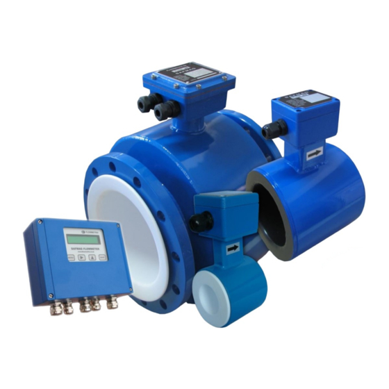
ACP HI-PULS METER
ELECTROMAGNETIC FLOW METER
(AC PULSED)
Safmag House
P.O.Box 17143
Int Tel.: +27(0)312060630
498 Sydney Road
Congella
SA Tel.: 086 110 6028
Congella
South Africa, 4013
enquiries@flowmetrix.co.za
Durban
Reg. No. CK 1986/011597/23
www.flowmetrix.co.za
Advertisement

Related Manuals for FLOWmetrix SAFMAG ACP HI-PULS METER

Summary of Contents for FLOWmetrix SAFMAG ACP HI-PULS METER
- Page 1 USER’S GUIDE Installation & Operation Instructions ACP HI-PULS METER ELECTROMAGNETIC FLOW METER (AC PULSED) Safmag House P.O.Box 17143 Int Tel.: +27(0)312060630 498 Sydney Road Congella SA Tel.: 086 110 6028 Congella South Africa, 4013 enquiries@flowmetrix.co.za Durban Reg. No. CK 1986/011597/23 www.flowmetrix.co.za...
- Page 2 INDEX Introduction Identification Application Inspection Damaged Parts Theory of Operation Description General Electronics Application Guidelines Conductivity Installation Piping and Other Considerations Meter Body Installation Procedure Electrical Connections Output Functions Start-up and Operation Factory Calibration and programming Calibration Coefficient Re-calibration Menu Organisation Troubleshooting Testing of Flow Specifications...
- Page 3 This manual covers the theory of operation, installation and field service procedures for SAFMAG electromagnetic flowmeters supplied with the ACP signal convertor. Should further support be required, contact your local representative or Flowmetrix SA directly. Identification Before beginning installation of the SAFMAG flowmeter, verify that all parameters of the intended application match those of the flowmeter supplied.
- Page 4 SAFMAG Electromagnetic Flowmeter Theory of Operation The operation of an electromagnetic flowmeter is explained by reference to Faraday’s law of electromagnetic induction. This law states that the voltage induced across an electrical conductor, as it moves at right angles through an electromagnetic field, is directly proportional to the velocity of that conductor through the field.
- Page 5 The ACP utilises a multi-tasking microprocessor to handle all functions simultaneously. The Flowmetrix philosophy of producing easy-to-use instrumentation means that the unit can be programmed in a matter of minutes, even without the instruction manual. The flow rate and total are displayed continuously on a backlit LCD display, clearly visible through the viewing window in the cast aluminium housing.
- Page 6 Application Guidelines The minimum flow velocity through the SAFMAG ACP magmeter at full scale (i.e. 20mA), should not be less than 1 metre/second. The meter diameter should therefore be selected accordingly. The SAFMAG ACP electromagnetic flowmeter has a minimum full-scale velocity of 1 metre/second and a maximum full-scale velocity of 10 metres/second.
- Page 7 Conductivity The first parameter to consider in deciding whether or not to use a magnetic flowmeter in a given application is conductivity. The conductivity unit of measure is microsiemens/cm or (µS/cm). The minimum conductivity level for the SAFMAG ACP is 20 µS/cm. Installation Piping and Other Considerations The SAFMAG ACP electromagnetic flowmeter should be installed in the pipeline with the...
- Page 8 NB: To ensure accurate flow measurement, the magmeter should be installed with at least 5 pipe diameters of straight pipe upstream, and 2 pipe diameters downstream of the magmeter. Meter Body The flowmeter should be lifted by a rope sling being passed around the outside of the meter or, in the case of the large meters the lifting lugs should be used.
- Page 9 Customer supplied grounding and connecting cables must have a cross section of 6mm be terminated with cable lugs. SAFMAG Flowmeters require the use of a special cable supplied by FLOWMETRIX SA for the connections between the meter body and the remote electronics display. Refer to the connection diagram for details.
- Page 10 fig a Measuring ground fig b Measuring ground fig c Measuring ground User’s Guide 2018...
-
Page 11: Remote Display
Wiring Diagram REMOTE DISPLAY Yellow E2 (Y) SCREEN Orange FLOWTUBE SCREEN White Yellow E1 (W) SCRN 4-20mA< /- Orange EARTH 4-20mA> /+ SCRN 0 VOLTS White OCT/PULSE 24 VOLTS Black COIL RELAY C White COIL RELAY NC RELAY NO CAL LINK CAL LINK Black COIL (B) - Page 12 Output Functions • The 4 – 20mA output signal is proportional to the flow rate. 4mA = 0 flow rate. The full- scale value (i.e. 20mA) is the flow rate figure programmed into menu item M1_2 & M1_3. OUTPUT ACP TERMINALS EXT.
- Page 13 Relay OUTPUT TERMINALS EXT. CIRCUIT SIGNAL Relay NC/NO Relay Output Relay contacts Relay (220VAC – Mechanical 0.27A, 24VDC – 2A) Totaliser COMMON Etc. User’s Guide 2018...
- Page 14 Before despatch the signal converter has been programmed, either to the factory standard or to those specifications advised by the customer. The SAFMAG ACP electromagnetic flowmeter has been calibrated at FLOWMETRIX flow laboratory with direct traceability to the National Standards. The flow sensor will hold its stated accuracy indefinitely provided that it is correctly installed and undamaged.
- Page 15 Menu Organisation With the SAFMAG ACP signal converter powered up flow total and flow rate are displayed 00000000 l 5.986 l/s Forward Total Forward Flow Flow Menu Password? * * * * Enter the required password. The flowmeter is shipped with the password 1000. (Default password = 1942).
- Page 16 MENU-1 Flow Data Menu-1 M-cont S-enter Press SAVE to enter or MENU to continue M1_1 rate units Press ▲ repeatedly until desired units are displayed and MENU to continue M1_2 max flow 100 l/s Enter the maximum forward flow rate at which to output 20mA Fwd current Press ►...
- Page 17 M1_7 cutoff 1%, 2%, 3%, 5% & 10% cutoff settings available Select the level below which the signal converter will output no flow Press ▲ to select option required and MENU to return to Main Menu M1_8 empty pipe activated/ deactivated Select to activate or deactivate empty pipe if required Press ▲...
- Page 18 MENU- 2 Setup Data Menu-2 M-cont S-enter Press SAVE to enter or MENU to continue. M2_1 dia mm Enter the nominal diameter of the flowmeter stamped on the flowtube. Press ► repeatedly until cursor is under digit to be edited Press ▲...
- Page 19 Press ▲ to select and MENU to continue M2_6 puls-width 10ms Provided the output pulse rate is less than 3.125 pps, the width can be varied. Press ▲ repeatedly until the desired value is displayed and MENU to continue NB: the pulse output will change to a frequency with equal on-off period for a pulse rate >3.125Hz.
- Page 20 Cal Mode To access the calibration menu enter the correct password and the press menu continuously until ‘Menu-2’ is displayed. Hold MENU key depressed for 5 seconds and the Cal mode menu will appear. Entry to Cal mode is only possible if the correct password has been entered, and if the MENU key is held depressed at the correct time.
-
Page 21: Troubleshooting
Troubleshooting Troubleshooting should be confined to establishing whether the fault lies in the flowtube assembly or in the signal convertor. The information provided should assist in this. The flowtube coils have a resistance of approximately 20Ω. All meters smaller than 600mm are supplied with the coils connected in series, giving a measured value of approximately 40Ω... - Page 22 Testing of Flowtube Always switch off power source before connecting and disconnecting cables. Use a multimeter to measure Check power to signal converter.Is led on voltage at coil terminals of triac on? flowtube. Approx 50% of supply voltage Signal converter faulty or wiring problem investigate.
- Page 23 Features & Specifications 0.1-10 m/s (0.33-33ft/s) Velocity Range Display and frequency output Accuracy ± 0.5% of rate for velocity > 0.5m/s ± 0.025% of full scale for velocity < 0.5m/s Repeatability ± 0.1 % of rate 40mm to 800mm (flanged format)PN10/16/25 IP68 Sensor size Response time 3 Selectable levels of damping...
-
Page 24: Warranty
The liability of Flowmetrix SA CC to the purchaser, except as to title, arising out of the supplying of the equipment or its use, under this warranty article, shall not, in any case, exceed the cost of correcting defects in the equipment as herein provided and upon the expiration of the warranty described herein, all such warranty liability shall terminate.
Need help?
Do you have a question about the SAFMAG ACP HI-PULS METER and is the answer not in the manual?
Questions and answers