Table of Contents
Advertisement
Quick Links
16
USER'S GUIDE
Installation & Operation
Instructions
ΒETA METER
ELECTROMAGNETIC FLOWMETER
Safmag House
P.O.Box 17143
Int Tel.: +27(0)312060630
498 Sydney Road
Congella
SA Tel.: 086 110 6028
Congella
South Africa, 4013
enquiries@flowmetrix.co.za
Durban
Reg. No. CK 1986/011597/23
www.flowmetrix.co.za
Advertisement
Table of Contents

Subscribe to Our Youtube Channel
Related Manuals for FLOWmetrix SAFMAG BETA METER

Summary of Contents for FLOWmetrix SAFMAG BETA METER
- Page 1 USER’S GUIDE Installation & Operation Instructions ΒETA METER ELECTROMAGNETIC FLOWMETER Safmag House P.O.Box 17143 Int Tel.: +27(0)312060630 498 Sydney Road Congella SA Tel.: 086 110 6028 Congella South Africa, 4013 enquiries@flowmetrix.co.za Durban Reg. No. CK 1986/011597/23 www.flowmetrix.co.za...
- Page 2 Cal Mode Modbus RTU Error Messages/ Troubleshooting Features & Specifications Testing of Flowtube Warranty Safmag House P.O.Box 17143 Int Tel.: +27(0)312060630 498 Sydney Road Congella SA Tel.: 086 110 6028 Congella South Africa, 4013 enquiries@flowmetrix.co.za Durban Reg. No. CK 1986/011597/23 www.flowmetrix.co.za...
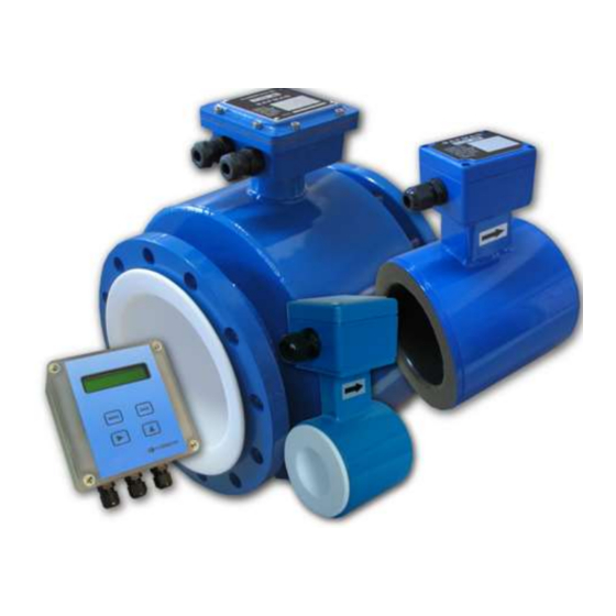
- Page 3 Introduction The Safmag β-meter provides cost effective measurement of flowrate in applications where mechanical flowmeters are traditionally utilized. The design concept has focused on simplicity, whilst retaining all benefits associated with the use of an electromagnetic flowmeter. The β-meter comprises a flowtube sensor and a display unit which is mounted remote from the sensor.
- Page 4 Installation guides Remote Electronics The remote electronics display may be mounted up to 100 metres from the meter body using SAFMAG cable. It should be mounted on the wall or a pipe stand. The display housings have dedicated points for mounting. DO NOT drill into the enclosure, this will void IP rating and warranty.
-
Page 5: Application Guidelines
Meter Body The flowmeter should be lifted by a rope sling being passed around the outside of the meter or, in the case of the large meters the lifting lugs should be used. Never pass a cable or beam through the flowtube for lifting purposes, as this will damage the flowtube liner and render the meter unusable. - Page 6 FLOW RATE GUIDE PIPE PIPE SIZE SIZE FLOWRATE @ 1m/s (3ft/s ) FLOWRATE @ 10m/s (30ft/s) (mm) (INCH) (l/s) m3/hr ft3/s gal(US)/s (l/s) m3/hr ft3/s gal(US)/s 0.08 0.28 0.003 0.02 0.78 2.82 0.03 0.21 0.18 0.64 0.006 0.05 1.76 6.36 0.06 0.46 0.02...
-
Page 7: Installation
Safmag Magprobe (Insertion mag) Flow rate = ( 0 – 6 m/s ) / ( 0 – 18 ft/s ) The insertion probe must only be installed with the flow in the direction of the arrow marking. The alignment of the probe is important for accurate flow measurement, and care should be taken to ensure that the point indicator on the terminal box mounting plate points along the axis of the pipe. -
Page 8: Remote Display
Wiring Diagram FLOWTUBE REMOTE DISPLAY BLACK WHITE COIL (B) YELLOW COIL E2 (Y) SCREEN COIL (W) BLACK COIL SCRN2 WHITE 24 Vdc ORANGE GND (O/B) PLS3 + Over All Screen WHITE GND (O/B) SCREEN PLS3 - SCRN SCRN1 SCREEN ORANGE PLS2 + EARTH E1 (W) -
Page 9: Output Functions
General The β-meter display/signal converter allows a fast response time for the sensors ≤150NB. This is achieved by automatically selecting higher coil frequencies permitting faster update times for flow calculations. These features allow batching of small volumes and ensure an acceptable accuracy. Size 50Hz Power Supply 60Hz Power Supply... - Page 10 OCT 1/2/3 OUTPUT BETA TERMINALS EXT. CIRCUIT SIGNAL 24V MAX PULSE – ISO GND 470Ω MIN External supply and PLS 1/2/3 0.05A MAX PLC IN pull up resistor PLC GND PLS - 0.8V 24V MAX PULSE – ISO GND Relay External supply and PLS 1/2/3 0.05A MAX...
- Page 11 Keypad System The β-meter has a 4-button programming system. From the run mode (after power up) The MENU button (M) is used to enter scroll through the menu structure. The SAVE button (S) is used to save entered changes to the flow meter programme.
- Page 12 START PROGRAMMING - Press MENU Main Menu The Main Menu consists of Batch? (if selected), Password?, Change?, Units?, Menu-1, Menu-2, and Save & exit Batch? M-no S-yes (only displayed if option selected) Press M to continue or S to enter the Batch Menu. Password? **** Enter the required password.
- Page 13 Batching Function (Set M1_8 to batch to activate batching, NB! use Save & exit) From normal run mode press M Batch? M-no S-yes Press S to enter the Batch Menu Batch Qty? 1000 Use ► and ▲ to move curser and select Batch Quantity e.g. 1000m3 or 100l. Total units are programmable in M1_5.
- Page 14 MENU-1 Flow Data M1_1 rate units Press ▲ repeatedly until desired units are displayed and M to continue M1_2 max flow 100l/s Enter the maximum flow rate at which to output 20mAPress ► repeatedly until cursor is under digit to be editedPress ▲ repeatedly until desired value is displayed and M to continue M1_3 alarm low Enter the minimum flowrate at which the alarm will activate...
- Page 15 M1_7 clr total Save total Select between clear tot to clear the existing flow Grand total and save tot to keep the existing flow Grand total or set tot to set Grand flow total to a determined start value.Press ▲ to select option required and M to continue.
- Page 16 MENU - 2 Setup Data M2_1 50/60Hz? 50Hz Operation Select the appropriate mains frequency. Press ▲ to select the option required and M to continue M2_2 sensor type flowtube / insertion mag Select between flowtube (fullbore sensors) or insertion mag (Safmag Magprobe) Press ▲...
- Page 17 M2_7 volume/pls 1.000 Enter the required output pulse rate liters/pulse Press ► repeatedly until cursor is under digit to be edited Press ▲ repeatedly until desired value is displayed and M to continue. M2_8 puls-width 20ms The output pulse width can be varied to 125 ms max. Press ▲...
- Page 18 Cal Mode (hidden menu) Cal mode is a hidden menu, for the setup of the current output and calibration. To access this menu the correct password must be entered, Step through the main Menu until Menu 2 is displayed, then press and hold M until Cal Mode? appears on the screen. Cal Mode M-cont S-enter...
-
Page 19: Control Functions
MODBUS RTU (Optional) The β-meter uses the MODBUS RTU protocol. This protocol defines a message structure that hosts and clients will recognize and use on the network over which they communicate. The MODBUS RTU uses a Master-Slave Query-Response Cycle in which the signal converter is the slave device. -
Page 20: Example Setup
Setup The MODBUS address is set up in Menu2_12 slave address. The address can be assigned 1 to 255. Address 1-100 Baud rate: 9600 Data bits: Stop bit: Flow control: None Parity: None Register and Coil Usage Data: Register: Access: Type: Offset Length... -
Page 21: Error Message
Error/Warning Messages ERROR MESSAGE ERROR POSSIBLE SOLUTION empty pipe No liquid in flowtube Fill pipe Faulty electrode / coil cable Repair / replace cable no coil current Faulty electrode / coil cable Repair / replace cable ... - Page 22 Features & Specifications Sensor size DN150..600 MXI PN 10/16 IP67, IP68 (optional) DN10..150 W PN 16 IP67, IP68 (optional) Accuracy +/- 0,5% of flow rate >0.5m/s Repeatability +/- 0,1% of flow rate >0.5m/s Range 0.1-10m/s Response Time 3 Selectable levels of damping Transmitter/Display β-meter remote wall mount IP67 Model No.
- Page 23 Testing of Flowtube Always switch off power source before connecting and disconnecting cables. Check Coil Voltage Switch off signal converter. Disconnect wires from coil term. at signal Remove flowtube terminal lid. Use AC voltmeter to measure voltage at the converter. Switch on and measure AC voltage coil terminals of flowtube.
- Page 24 Testing (continued) SYMPTOM : Excessive noise on signal cable. Flow displayed when zero flow. Check screening and earthing, look for Is flow tube empty? loose wires, poor insulation, shorts between any wires/screens. Increase % cut off if unable to eliminate noise completely.
-
Page 25: Warranty
The liability of Flowmetrix SA CC to the purchaser, except as to title, arising out of the supplying of the equipment or its use, under this warranty article, shall not, in any case, exceed the cost of correcting defects in the equipment as herein provided and upon the expiration of the warranty described herein, all such warranty liability shall terminate.
Need help?
Do you have a question about the SAFMAG BETA METER and is the answer not in the manual?
Questions and answers