Table of Contents
Advertisement
Quick Links
Advertisement
Table of Contents
Troubleshooting

Related Manuals for QTech SMS Lite

Summary of Contents for QTech SMS Lite
- Page 1 SMS Lite 4G User Guide SMS Lite 4G Version 2.3...
-
Page 2: Table Of Contents
Status LED ........................16 Status Indication ........................16 Error Code Indication......................16 Troubleshooting ......................17 Performing a Verification Test ....................17 Troubleshooting Tips ...................... 19 General Tips and Information ..................20 SMS Lite 4G– User Guide © 2022 QTech Data Systems Ltd... - Page 3 Active Alarm Interruption ....................... 21 Error Message ........................21 Case Sensitivity ........................21 Technical Specifications ....................22 SMS Lite Specification ......................22 Configuration Worksheet ....................23 Warranty ........................24 Additional Information and Support ................24 SMS Lite 4G– User Guide...
- Page 4 The information in this document is subject to change without notice and does not represent a commitment on any part of QTech Data Systems Limited. While the information contained herein is assumed to be accurate, QTech Data Systems Limited assumes no responsibility for any errors or omissions.
-
Page 5: About This User Guide
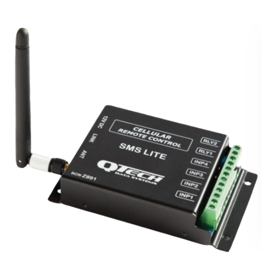
Product Overview The SMS Lite is a cellular remote-control device that uses text messages to provide up to four people with status conditions, notifications, and control options for its four switched inputs and two relay outputs. -
Page 6: Getting Started
The SIM card must be a standard “full size” card, not a micro or nano SIM. We recommend you insert the SIM into a regular cell phone and check that you can send and receive messages. Carefully remove the SMS Lite cover by prising the side panels close to the retaining dimples. -
Page 7: Inputs
Inputs The SMS Lite inputs are to be connected to switches or mechanical contacts. The default input names are: INP1, INP2, INP3, INP4, which can be renamed. An input is active or ON when the input switch is closed and inactive or OFF when the input switch is open. -
Page 8: Basic Configuration
Basic Configuration To operate the SMS Lite, the device must have a mobile number registered as ‘Phone 1’ referred to as Ph1. You must register this number before you can configure any of the inputs or outputs. The SMS Lite can have up to 4 phone numbers registered. -
Page 9: Connect The I/O
Where the units can be ms, sec, min, or hr, and the maximum duration is 1 day. This is all that is required for the master phone number to receive notifications from the SMS Lite inputs and control the outputs. -
Page 10: Additional Configuration
You can assign a site name as well as naming each of the inputs and outputs and assigning phone(s) to these. The SMS Lite can be configured with up to 4 phone numbers allowing multiple user notifications and control options. -
Page 11: Escalations
To program the Site name to Shed1, name Input 1 as Pump and set notification escalations to phones 1, 2 and 3. You can either send the SMS Lite 3 individual configuration text messages: e.g. -
Page 12: Advanced Commands
You can program a delay before the text message is sent by the SMS Lite. The trigger point / device that is connected to the SMS Lite must stay in that state for the ‘debounce’ time that is set, before the SMS Lite will send a text message alerting you of a status change. -
Page 13: Message Paths
Message Paths The following diagrams are examples of the message flows for the SMS Lite. They show the basic message flow, an example of a busy response, no response and the escalation flow to multiple phones. Example 1 - Phone 1 Alerted – Alarm Acknowledged... -
Page 14: Alarms
It will begin at the top of the list the next time the input is activated. To force the SMS Lite to send the alarm message to the next phone number in the list. BUSY <input name> (e.g. Text: BUSY Pump) Up to 3 other phones can be programmed to receive a notification. -
Page 15: Information Commands
The SMS Lite will inform you of the version of firmware it is running. TEST e.g. Text: TEST This is a quick check to see if the SMS Lite is operational. It will display a led sequence and send the response: “SMS-Lite comms test succeeded!”... -
Page 16: Output Control
Heartbeat – 1 short flash every two seconds - the SMS Lite is connected to the cellular network. Transmit OK – 5 short flashes - shows the SMS Lite successfully sent an SMS. Transmit Fault – 3 long flashes - shows the SMS Lite tried to send but there was a problem. Error Code Indication The LED also indicates error codes that can be used to help identify issues: Error Code 1 - 2 flashes - indicates the Modem will not power up. -
Page 17: Troubleshooting
6. The device is running on older firmware which can result in issue number 3 above. There are some actions that can be taken to assist QTech with diagnosing the issue. These involve carefully noting the actions of the indicator LED as it powers up and also counting the number of pulses in an error code when it is displayed. - Page 18 If the device fails to do either or both of these, then there is a fault. If a fault error code is being flashed, see the previous section on Status LEDs to diagnose the fault, or contact QTech for assistance after working through the troubleshooting tips below.
-
Page 19: Troubleshooting Tips
SIM. Then replace the SIM into the SMS Lite and power it up. This issue might also be resolved by upgrading to the latest version of firmware. -
Page 20: General Tips And Information
Upgrading from the old 2.5G SMS Lite. Take care when transferring the old SIM card to the new 4G SMS Lite. If the new 4G SMS Lite fails to register on the mobile network, shown by error code 4, you may need to obtain a new SIM card compatible with the 4G network. The modem type is identified by the following printing on the daughterboard: “UC864-G”... -
Page 21: Programming Tips
By sending ‘Status’ to the SMS Lite you can see the status of any of the inputs or outputs, this can help identify if the alarm escalation has been interrupted by a configuration change. -
Page 22: Technical Specifications
Output Current: 2A max. Detachable SMA Modem Antenna Max. Cable length 6m (low loss RG57) 3G Bands (MHz) B1(2100), B5(850), B8(900) 4G Bands (MHz) B1(2100), B3(1800), B5(850), B8(900) B28(700) SMS Lite 4G– User Guide © 2022 QTech Data Systems Ltd... -
Page 23: Configuration Worksheet
Program the phones which will be included in each input escalation, if required. Output 1 Output 2 e.g. Name: Phones: Ph1,Ph2,Ph4 Program the phones which will have permission to control outputs. Additional sheets can be downloaded from our website: https://qtech.co.nz SMS Lite 4G– User Guide © 2022 QTech Data Systems Ltd... -
Page 24: Warranty
Warranty The SMS Lite hardware and software is covered by QTech Limited Warranty Agreement and software End User License Agreement, respectively. Please refer to the QTech Limited Product Warranty Agreement, which may be downloaded from the QTech website: www.qtech.co.nz QTech Data Systems Limited does not warrant the suitability of this product for any particular application as the conditions in which it is used are beyond our control.
Need help?
Do you have a question about the SMS Lite and is the answer not in the manual?
Questions and answers