Advertisement
Advertisement
Table of Contents

Related Manuals for BVL Controls ECO-025

Summary of Contents for BVL Controls ECO-025
- Page 1 BVL Power Pack Service & Specification Manual Manufactured by BVL Controls Ltd...
-
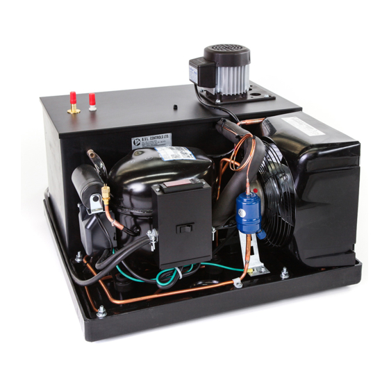
Page 2: Air Cooled
BVL POWER PACK Manufactured by BVL Controls Ltd AIR COOLED ECO-025 1/4 HP R-134a 120 VAC ECO-033 1/3 HP R-134a 120 VAC BVL-056 1/2 HP R-134a 120 VAC CMC-030 1/3 HP R-134a 120 VAC CMV-030 1/3 HP R-134a 120 VAC... - Page 3 DESCRIPTION CWA-3 CWA-2 CWW-2 CWA-34 CWW-34 Voltage AC 208/230 208/230 15 A + 15 A + 15 A + 15 A + 20 A, if 2 1 pump 15 A or 1 pump 15 A or Circuit Breaker 1 pump 15 A or 1 pump 15 A or pump + 15 A 2 pumps 20 A or...
- Page 4 ECO-025 ECO-033 BVL-056 CMC-030 CMV-030 Voltage AC Circuit Breaker 15 A 15 A 15 A 20 A 20 A Plug (NEMA) 1 x 5-15P 1 x 5-15P 1 x 5-15P 2 x 5-15P 2 x 5-15P Running 5.82 A 8.5 A 5.82 A...
- Page 5 CWA-100 CWA-100 CWA-100 CWA-175 CWA-175 CWA-175 2 pumps 3 pumps 4 pumps 2 pumps 3 pumps 4 pumps Voltage AC 208/230 208/230 208/230 208/230 208/230 208/230 Circuit Breaker 20 A 20 A + 20 A 20 A + 20 A 20 A 20 A + 20 A 20 A + 20 A...
- Page 6 DRAWINGS ECO-033 Double/Triple Motor Bath Option, Used With CWA or CWW Top view for CWA-3, CWA-2, CWA-34 (and also CWW units) 2 PUMPS 3 PUMPS Triple/Quadruple Motor Bath Option, Used With CWA-100 and 175 Top view for CWA-100 and CWA-175 2 PUMPS 3 PUMPS 4 PUMPS...
-
Page 7: Product Warranty
PRODUCT WARRANTY BVL Controls warrants this product for one (1) full year including parts and labor when unit is returned to our factory (freight is not part of the warranty) or parts only when repair must be done at another location. Parts (under warranty) will be charged to your account and will be credited upon receipt of the defective part. - Page 8 INSTRUCTIONS FOR THE INSTALLATION ECO-025/ECO-033 1 : The supply voltage required for the unit is 120 VAC with a 15 A circuit breaker. 2 : For a proper functioning of the machine, leave a 6’’ (15 cm.) minimum clear space around the condenser to facilitate air flow.
- Page 9 INSTRUCTIONS FOR THE INSTALLATION CMC-030/CMV-030 1 : The supply voltage required for the unit and the pump is 120 VAC with a 20 A circuit breaker. 2 : For a proper functioning of the machine, leave a 6’’ (15 cm.) minimum clear space around the condenser to facilitate air flow.
- Page 10 INSTRUCTIONS FOR THE INSTALLATION CWA-2 1 : The supply voltage required for the unit is 120 VAC with a 15 A circuit breaker. If there is one pump, provide an additional 15 A circuit breaker. If there are 2 pumps, provide instead an additional 20 A circuit breaker.
- Page 11 INSTRUCTIONS FOR THE INSTALLATION CWA-3 1 : The supply voltage required for the unit and one pump is 120 VAC with a 20 A circuit breaker. If there is an extra pump, provide an additional 15 A circuit breaker. 2 : For a proper functioning of the machine, leave a 6’’ (15 cm.) minimum clear space around the condenser to facilitate air flow.
- Page 12 INSTRUCTIONS FOR THE INSTALLATION CWA-34 1 : The supply voltage required for the unit is 208/230 VAC with a 15 A circuit breaker. For 1 pump, the supply voltage required is 120 VAC with a 15 A circuit breaker. For 2 pumps, the supply voltage required should be instead 120 VAC with a 20 A circuit breaker.
- Page 13 INSTRUCTIONS FOR THE INSTALLATION CWA-100/CWA-175 1 : The supply voltage required for the unit is 208/230 VAC with a 20 A circuit breaker. For 2 pumps, the supply voltage required is 120 VAC 20 A. If your installation requires 3 or 4 pumps, provide an additional 20 A circuit breaker.
-
Page 14: Maintenance
MAINTENANCE Keep liquid level constant in glycol reservoir. Glycol should be changed every year except in very hot areas where it should be changed every six (6) months. 1. Check liquid monthly a. If level is low, fill with water; b. -
Page 15: Troubleshooting
TROUBLESHOOTING If the control system does not function properly, verify that the unit is wired, configured and set properly. If the problem persists, use the following procedures to determine the cause of the problem: Check for proper supply voltage to thermostat. WARNING: Risk of Electrical Shock. - Page 16 TROUBLESHOOTING 4- Warm beer A- Defective pump. A- Check returns line in reservoir for liquid (Check motor also) flow. Replace pump. B- Defective motor. B- Replace motor. (Check pump also) C- Refrigeration unit is not C- Refer to 2 running. D- Conduit lines located in D- Remove from any hot water pipes or overheated area.
Need help?
Do you have a question about the ECO-025 and is the answer not in the manual?
Questions and answers