
Related Manuals for HTA HT2800T

Summary of Contents for HTA HT2800T
- Page 1 User Guide HT2800T All-in-ones GC Autosampler: Headspace, Liquid and SPME HT2800T_en_c.doc www.hta-it.com...
- Page 2 All rights are reserved. Manufacturer: HTA s.r.l. - 77-79, via del Mella, I-25131 Brescia (BS), Italy - Tel: +39 030 3582920 - E-mail: info@hta-it.com HT2800T_en_c.doc...
-
Page 3: Table Of Contents
) ..........20 OFTWARE EQUIREMENTS UTOSAMPLER ANAGER EQUIPMENT DESCRIPTION ....................21 ......................21 ARTS EFINITION 2.1.1 HT2800T/HT2850T Overview ......................21 2.1.2 Syringe location ..........................27 2.1.3 Connection panel ..........................35 ........................36 OVING PARTS ..........................37 OOL KIT .................. 38 OUCH SCREEN DISPLAY DESCRIPTION 2.4.1... - Page 4 .......................... 60 TART ..............61 CONNECTION AND SOFTWARE INSTALLATION 3.5.1 Autosampler controlled by LAN-connected PC ................61 3.5.2 Autosampler connected directly to the PC ..................70 ....................71 CCESSORIES INSTALLATION 3.6.1 External pressure regulator installation (only for Headspace and SPME mode) ....71 3.6.2 Swagelok Adapter installation (only forHeadspace and SPME mode) ........
- Page 5 5.3.1 Method Menu ..........................147 5.3.2 Method X: Setting method parameters ..................147 5.3.3 Method tools ..........................153 5.3.4 Example ............................153 PROGRAMMING SEQUENCE....................155 ..................155 EQUENCE EADSPACE MODE 6.1.1 Sequence Menu ..........................155 6.1.2 Setting sequence step parameters ....................155 6.1.3 Sequence tools ..........................
- Page 6 7.10.1 Change from Headspace to Liquid mode .................. 175 7.10.2 Change from SPME to Liquid mode ..................182 7.10.3 Change from Liquid to Headspace mode .................. 189 7.10.4 Change from Liquid to SPME mode ..................195 7.10.5 Change from Headspace to SPME mode .................. 201 7.10.6 Change from SPME to Headspace mode ..................
- Page 7 8.17.1 Tray opening by hand ....................... 222 8.18 “HTA A ” ............224 UTOSAMPLER ANAGER TROUBLESHOOTING 8.18.1 Autosampler and PC do not communicate (connection by LAN) ........224 8.19 ..................226 NALYTICAL TROUBLESHOOTING 8.19.1 Analytical troubleshooting (Headspace Mode)................. 226 8.19.2 Analytical troubleshooting (Liquid Mode) ................
- Page 8 12.3 SPME ..................266 ONSUMABLES FOR MODE 12.3.1 Fibers ............................266 12.3.2 Washing vial ..........................266 APPENDIX C – ANALYZER CONNECTOR ................ 267 13.1 RS232C ) ..................269 INTERFACE OPTIONAL HT2800T_en_c.doc Page 8 of 275...
-
Page 9: Introduction
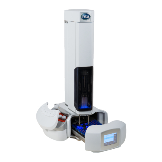
1 Introduction 1.1 Intended Use and Restrictions HT2800T is an all-in-ones GC autosampler for static Headspace analysis, liquid sample injection and SPME. The autosampler must be used in a professional environment, and only by properly trained users. The autosampler must be used according to the regulations in force regarding the safety in testing laboratories. -
Page 10: Symbol Table
Any other use may affect the autosampler and operator safety. HTA s.r.l. is not responsible for damage caused, even only in part, by improper use of the autosampler, by unauthorized modification of it, by different or missing execution of the procedures described in this manual, or by the use of the autosampler violating the applicable laws and regulations. -
Page 11: Warning
HTA representative. The power cord connector is considered the disconnecting device of the product. Electrical damage may have occurred if the autosampler shows visible signs of damage, or has been transported under severe stress. - Page 12 If there is any doubt about the method for proper use of cleaning or decontamination agents contact a HTA representative. With regards to autosampler recycling and disposal the following operations mus be performed in the proper order: 1) remove syringe, samples and reagents;...
- Page 13 If, during the start up process or while the running the machine, you notice unusual noises or vibrations, stop the operating process and contact the Technical Assistance Centre. The warning signals presented on the turret and on the oven cover indicate the presence of moving parts, including the syringe and the fan.
-
Page 14: Standards Compliance
2006/42/EC Machinery Directive. 1.5 General Specification This is an autosampler for gas chromatography. The HT2800T combines the functions of an autosampler for liquid, static Headspace and SPME into a single unit. The autosampler is compatible with most Gas Chromatographs (GC). -
Page 15: Functions Available Only Through
The Vial leakage test can discriminate for samples which are correctly sealed vs. bad crimping or missing septa. Each sample is marked with PASS or FAIL information in HTA Autosampler Manager Windows. -
Page 16: Options
For detailed description of this function see paragraph 11 “Appendix A – Glossary”. 1.91.734 - Bar Code Reader Module HT2800T (Factory installation) This may be sold as an option. This is not compatible with RS232C interface option. -
Page 17: Technical Specifications
10kg HT2850T 10kg ELECTRICAL SPECIFICATIONS Power supply: Voltage 100-240 ±10%Vac Frequency 47-63Hz Max Current 1.6 A Autosampler HT2800T/HT2850T: Voltage 24Vdc Power 120W INTERFACE SPECIFICATIONS To GC To PC Ethernet 10/100 Optional: RS232C (available on a limited number of models) Ethernet cable should be Category 5 (or higher) RS232 cable: max distance PC –... - Page 18 ENVIRONMENT CONDITIONS Room temperature limits 15° C - 35° C Ambient humidity limits 5% - 80% (not-condensable) Maximum altitude 2000m SOUND PRESSURE LEVEL Maximum measured level 60dBA (below the limits of 85dBA defined by the regulations in force) SAFETY INFORMATION The autosampler is classified as shown below: Pollution degree Overvoltage category Devices for use indoors...
- Page 19 Injection speed from 0.5 to 100ml/min (40ml/min for 1ml syringe) Pre/Post injection dwell time from 0 to 99secs Enrichment cycles up to 15 Dwell time between enrichment cycle from 0 to 100min Syringe purge Flush time from 0 to 99min Purge temperature off, from 40°...
-
Page 20: Pc Software Requirements (Hta Autosampler Manager)
Shaking cycles on/off, from 0 to 9.9min 1.9 PC Software Requirements (HTA Autosampler Manager) See HTA Autosampler Manager Online Help for the related PC specifications. Warning The virtual screen is available only with LAN connection. It is not available with RS232 connection. -
Page 21: Equipment Description
2 Equipment Description 2.1 Parts Definition HT2800T/HT2850T Overview 2.1.1 Figure 1 : Top view (tray open) Figure 2: Top view (tray closed) 1. MOVING TRAY (1 rack with 42 sample positions in the Headspace Mode or 1 rack with 121 sample positions in Liquid Mode) 2. - Page 22 FIBER WASHING VIAL. 2.1.1.1 HT2800T/HT2850T Sample rack In Headspace mode and SPME mode HT2800T mounts a 42-position rack (20,10 or 6ml vials). Figure 3: 42 position rack (Headspace and SPME) Each vial is identified with two digits (a letter and a number): HT2800T_en_c.doc...
- Page 23 Number (column) The letters (from A to G) indicate the rows, while the numbers indicate the columns (from 1 to 6). In Liquid Mode HT2800T mounts a 121-position rack (2ml vials). Figure 4: 121 position rack (liquid mode) Each vial is identified with two digits (a letter and a number):...
- Page 24 When configured for SPME the “A” position is used for the derivatizing agent. If 10 or 6ml sample vials are used instead of 20ml sample vials the proper spacers must be installed in the oven positions. In the liquid mode this oven represents the location for solvent vials. The solvent vial positions are labelled A-F.
- Page 25 Figure 5: HT2800T/HT2850T Incubation oven/ Location for solvent vial In the left figure, the oven is shown open, while in the right figure it is shown closed. HT2800T_en_c.doc Page 25 of 275...
- Page 26 The touch screen display is on the front of the unit. Figure 8: Touch screen display The HT2800T/HT2850T has a colour LCD display with touch control. The touch screen display can be used to edit the method, sample list or set up as well as running the samples.
-
Page 27: Syringe Location
2.1.2 Syringe location The syringe is located in the turret. To access the syringe, push up the sliding lid (red arrow in the figure below). Figure 9: Sliding lid down Figure 10: Sliding lid up HT2800T_en_c.doc Page 27 of 275... - Page 28 2.1.2.1 Syringe location for Headspace mode The syringe location contains the following parts: Figure 11: Syringe location (Headspace mode) Syringe warmer assembly: installed (left), not installed (right) Plunger holder with plunger locker Retaining nuts Needle height regulator (right block) Syringe connection socket Flushing gas inlet Vial locator Safety lock (left block)
- Page 29 The syringe warmer assembly and the vial locator are shown in detail in the figures below: Figure 12: Syringe warmer assembly (Headspace mode) Figure 13: Vial locator (Headspace ans SPME mode) The plunger locker has two different faces in order to locate different kinds of syringe pistons. These faces are indicated as “S side”...
- Page 30 2.1.2.2 Syringe location for Liquid Mode The syringe location contains the following parts: Figure 16: Syringe location (liquid mode) Figure 17: Syringe location (liquid mode with syringeID system installed) HT2800T_en_c.doc Page 30 of 275...
- Page 31 The syringe location contains the following parts: 1. Syringe holder 2. Needle height regulator (right block) 3. Plunger holder with plunger locker 4. Syringe locker 5. Safety lock (left block) 6. Intermediate needle guide 7. Vial locator The syringe holder is shown in detail in the following figure: Figure 18: Syringe holder (liquid Figure 19: Syringe holder (liquid mode with mode)
- Page 32 The syringe locker and its finger screws are shown in detail in the following figure: Figure 20: Syringe locker (liquid mode) The plunger locker has two different faces to locate different kinds of syringe pistons. These faces are indicated as “S side” and “B side”. When “S side” is required, please have “S side” facing down; when “B side”...
- Page 33 This vial locator can be removed and replaced with the vial locator with gripper shown in the picture below: Figure 24: Vial locator with gripper This vial locator must be installed in case that you want to enable Bar code reader option (0 “Select “Exit”...
- Page 34 Figure 25: Fiber holder location (SPME mode) Fiber holder Needle height regulator (right block) Safety lock (left block) Vial locator Plunger locker The vial locator are shown in detail in the figures below: Figure 26: Vial locator (Headspace and SPME mode) HT2800T_en_c.doc Page 34 of 275...
-
Page 35: Connection Panel
The plunger locker has two different faces in order to locate different kinds of syringe pistons. These faces are indicated as “S side” and “B side”. When “S side” is required, please have “S side” facing down; when “B side” is required, please have “B side” facing down. In the SPME mode side B must be faced downward. -
Page 36: Moving Parts
Service Ethernet reset: reserved for Service Representative Service Emergency release: reserved for Service Representative Gas connection for syringe purge: inlet 1/8” N.B.: For further information on this purge line connection please refer to paragraph 3.3.4 “Purge line connections (for Headspace and Fiber Cleaning Device)”. Warning Use only the power supply system supplied with the autosampler. -
Page 37: Tool Kit
• The oven cover can rotate 35° (open/close position); • The orbital shaker allows vial(s) agitation with a programmable speed. • The fan is used to assist temperature stabilization and the cooling down of the oven. The movements are made with DC motors, with position control made by encoders. Warning If necessary, it is possible to move the turret and needle motors by hand, very carefully, but only when the autosampler is switched off. -
Page 38: Touch Screen Display Description
HT2800T/HT2850T use touchscreen displays. These can be controlled using your finger tip or with a dedicated stylus. Only use a stylus approved by HTA as using any other stylus (or a pen or pencil), may scratch and damage the touchscreen. - Page 39 the enabled buttons use a white font and the disabled buttons use grey font; a button could ➢ be disabled because the associated action is not allowed or because other actions must be completed first; when a button has been tapped, the background becomes blue for a while. ➢...
- Page 40 Figure 35: Screen type 1_example A Figure 36: Screen type 1_example B In this menu, there are up to 6 buttons available. Tap one of the buttons to enter the respective menu/sub menu/function. Special icons: • ARROW (see example B, green circle). If more than 6 buttons are available, an ARROW icon is displayed, press this to access the additional buttons..
- Page 41 Select “EXIT” (red circle) to exit from this screen. “EXIT” is always the last option on the list; if the list includes a large number of items you may be required to press the “DOWN arrow” several times to reach the “EXIT” option. 2.4.1.4 Screen type 4: Parameter editing Screen type 4: Figure 38: Screen type 4...
-
Page 42: Limited Warranty
The grey area shows a notification/confirmation message. The lower part of the screen shows the action buttons. These include: • “SAVE” to store the editing, • “CANCEL” to exit without saving, • “CONTINUE” to confirm, • “STOP” or “ABORT” to interrupt the procedure •... - Page 43 spot, bright spot, pinhole, black line, white line, contrast variation, glass defect, polarizer defect, etc.. The minor defects do not give right to repair or part substitution under warranty, unless the number of minor defects substantially degrades the product application. HT2800T_en_c.doc Page 43 of 275...
-
Page 44: Installation
Warning The autosampler must be located in a place that provides good ventilation. The HT2800T/HT2850T oven is equipped with a fan, which is used to assist temperature stabilization and the cooling down of the oven. This fan must not be obstructed as it may affect the operation of the unit. -
Page 45: Autosampler Assembly
Warning Do not switch the autosampler on before it is correctly mounted on the bracket (see paragraph 3.3.1 “Autosampler installation on the mounting plate” to avoid the risk of overturning. 3.2 Autosampler Assembly 1. Open the box. Figure 43: Open the box 2. - Page 46 3. Extract the autosampler from the box and place it on a flat surface in a vertical position. Figure 45: Extract the autosampler from the box Figure 46: Place the autosampler on a flat surface 4. Cut the adhesive tape to open the packaging. Figure 47: Cut the adhesive tape 5.
- Page 47 Figure 48: Remove the upper cushions 6. Remove the accessory boxes and extract the included accessories. Figure 49: Remove the accessory boxes 7. Remove the lower protective cushions. Figure 50: Remove the cushions HT2800T_en_c.doc Page 47 of 275...
- Page 48 8. Check the product sheet to verify that the autosampler configuration (left or right) is consistent with your GC (see paragraphs 2.1.1.4 “HT2800T/HT2850T Control panel: touch screen display”). If the configuration of the autosampler is not correct with respect to your GC specification, please contact your local supplier.
-
Page 49: How To Lift And Carry The Autosampler
3.2.1 How to lift and carry the autosampler Warning Before lifting and moving the autosampler it is necessary to remove all of the removable elements: vials and rack. The autosampler must be lifted and carried by hand as shown in the following figure: Figure 54: How to lift and carry the autosampler 3.3 Installation Please read this chapter before using the autosampler . - Page 50 2 . 1 . 1 . 1 “ HT2800T/HT2850T Sample rack, paragraph 7.7 “Load and Unload Sample Vial” to open the tray and paragraph 7.9.1.1 “Rack mounting” to correctly mount the rack). Perform the touch and plunger zero procedure (see paragraph 0 “ 4.2.1 “Setup: Alignment”).
-
Page 51: Autosampler Installation On The Mounting Plate
7 . 1 0 . 1 “ Change from Headspace to Liquid mode” At the end of the change mode procedure, it is always necessary to adjust the injector alignment (see point below). 16. Align the autosampler on the GC Injector(s) (see paragraphs 4 . 2 . 1 . 2 “ Alignment: Front Injector”... - Page 52 Figure 55: Example of a mounting plate correctly mounted on a GC HT2800T_en_c.doc Page 52 of 275...
- Page 53 3. Open the mounting plate locker, pulling it out using the syringe pointer shown in the Figure 31. The opening procedure is shown in the figures below. Figure 56: Mounting plate locker opening (example) HT2800T_en_c.doc Page 53 of 275...
- Page 54 4. Place the autosampler over the mounting plate, ensuring that the four rubber feet of the autosampler (indicated with “X” in Figure 6) fit the four plate holes in Figure 55: Figure 57: Autosampler mounting over the mounting plate Fix the autosampler on the plate, closing the locker and pulling it in. Figure 58: Mounting plate locker closing HT2800T_en_c.doc Page 54 of 275...
- Page 55 3.3.1.1 Unlock the autosampler from the mounting kit 1. Open the mounting plate locker, pulling it out using the syringe pointer shown in Figure 31. The opening procedure is shown in the figure below. Figure 59: Mounting plate locker opening 2.
-
Page 56: Safety Lock Setting
3. Close the mounting plate locker, by pushing it in. The plate returns as shown in Figure 3.3.2 Safety Lock setting When shipped the autosampler has the safety lock as shown in the first of the following pictures; to work correctly it should be set as shown in Figure 61: Figure 60: Shipping position Figure 61: Moving from shipping to operating position Figure 62: Operating position HT2800T_en_c.doc... -
Page 57: Electrical Connections
1 Needle Guide regulator (right block) 2 Safety lock (left block) 3 Vial locator Warning If you don’t adjust the safety lock, after start up the autosampler will display an error message (see paragraph 8 Troubleshooting8 “Troubleshooting“). For an accurate first installation, do not release the needle guide regulator –... -
Page 58: Purge Line Connections (For Headspace And Fiber Cleaning Device)
Proceed as follows: 1. Connect the analyzer to its connector (number 5 in Figure 29) (15 pin port) using the interface cable provided with the mounting kit. 2. Insert the power cable inside the socket (number 2 in Figure 29). This cable is connected to an external power supply (low voltage) (see paragraph 2.1.3 “Connection panel”). -
Page 59: Preparing The Solvent And Waste Vials (Liquid Mode)/ Preparing The Washing Vial (Spme Mode)
Purge gas requirements Purity Notes Helium 99.9995% Hydrocarbon free Nitrogen 99.9995% 3.3.5 Preparing the solvent and waste vials (liquid mode)/ Preparing the washing vial (SPME mode) Warning These operations must be completed by competent personnel, properly trained about the procedures described in this manual: any missing or different execution of the described procedures can cause damages to the autosampler or to the person. -
Page 60: Start-Up
3.3.5.3 Cleaning • Remove the vials (see above). • Carefully remove the plastic caps and septa. • Empty and wash the glass vials and the plastic caps. • If necessary, change the septa. • Refit the caps and septa on the vials as described in the “Mounting“ (see above). •... -
Page 61: Pc Connection And Software Installation
HTA Autosampler Manager”. Warning HTA Autosampler Manager comes in two versions: Standard version and CFR 21 Part 11 version. In the document in which is reported the Activation key you will find information about the version for which you have been granted a license. - Page 62 “HTA Autosampler Manager” and the autosampler (see paragraph 3.5.1.1 “Default IP address “). 3) Install “HTA Autosampler Manager” on the PC. "HTA Autosampler Manager" is provided on the CD supplied with the instrument. Follow the wizard to install the software (self- explaining).
- Page 63 5) (For HTA Autosampler Manager CFR 21 Part 11 version only). At the first access of the software the activation licence is required (click on “Add” from figure “a”, tab “Licences” enabled). Then Administrator creation is required (click on “Add” from figure “b”, tab “Users”...
- Page 64 Figure 65: HTA Autosampler Manager screenshot 1 7) From the following screen, click on “Next”: Figure 66: HTA Autosampler Manager screenshot 2 8) Give a “Name” to the instrument in order to identify it more easily, and then click on “Next”: Figure 67: HTA Autosampler Manager screenshot 3 9) Confirm the instrument is connected by "TCP/IP port"...
- Page 65 Figure 68: HTA Autosampler manager screenshot 5 10) All the instruments currently connected by Ethernet (LAN) are shown in the following screen. Click on one instrument and then on "Next". If your instrument is not found you can re-try pressing “Refresh”.
- Page 66 Figure 70: HTA Autosampler manager screenshot 5 12) Fill in the form with the analyzer data. Click on “Next”: Figure 71: HTA Autosampler Manager screenshot 11 13) Insert the Activation key supplied with the instrument: HT2800T_en_c.doc Page 66 of 275...
- Page 67 Figure 72: HTA Autosampler Manager screenshot 12 14) The ending of the activation procedure depends on your type of Internet connection: a) If you have an Internet connection (not via Proxy server) an automatic activation starts. b) If you do not have an internet connection available on the PC you are working with, click on “Activate offline”.
- Page 68 The following window appears: Figure 74: HTA Autosampler Manager screenshot 12 -If you already have a “licence key”: select “I have a licence key” and then insert it in the dedicated field. -If you do not have a “licence key” select “I need a licence key” and then “Request licence key”.
- Page 69 Figure 76: HTA Autosampler Manager screenshot 18 3.5.1.3 IP address/Subnet mask modification If it necessary to modify the IP address/Subnet mask proceed as follows: 1) Connect the autosampler directly to the PC, inserting the Ethernet cable provided with the autosampler in the port indicated with the number 4 in Figure 29 and then into the Ethernet port of the PC (see paragraph 3.3.3 “Electrical connections“);...
-
Page 70: Autosampler Connected Directly To The Pc
Figure 77: P address/Subnet mask modification 5) Follow the wizard to end the procedure (the instrument has to be switched off/on). If a communication problem occurs, close the software and run it again. 3.5.2 Autosampler connected directly to the PC 3.5.2.1 Autosampler connected directly to the PC by the Ethernet port 1) Connect the autosampler directly to the PC, inserting the Ethernet cable provided with the autosampler in the port indicated with the number 4 in Figure 29) and then into the Ethernet... -
Page 71: Accessories Installation
3.6 Accessories installation Warning During Headspace and SPME operation the syringe is cleaned after each injection with inert, 3.6.1 External pressure regulator installation (only for Headspace and SPME mode) This optional accessory is used to regulate the pressure of the gas used for the syringe flushing (e.g. -
Page 72: Swagelok Adapter Installation (Only Forheadspace And Spme Mode)
Figure 80: External pressure regulator connection 3.6.2 Swagelok Adapter installation (only forHeadspace and SPME mode) 1) Use a Hexagon key (2mm) to unscrew the Rapid fitting terminal (indicated with the letter A in the figure below): HT2800T_en_c.doc Page 72 of 275... -
Page 73: System Integrity Tool Installation (Only For Headspace Mode)
(indicated with the letter D in the figure below): Figure 83: Swagelok adapter installation_3 3.6.3 System integrity tool installation (only for Headspace mode) This tool is included in the GLP Pack for HT2800T/HT2850T (see paragraph 1.7.2 “Options”). HT2800T_en_c.doc Page 73 of 275... - Page 74 4) Remove the upper part of the Syringe integrity tool (as indicated in the figure below): Figure 84: System integrity tool installation_1 5) Insert the septum (indicated with the letter A in the figure below) in the lower part of the Syringe integrity tool: Figure 85: System integrity tool installation_2 6) Screw by hands the upper part (indicated with the letter B in the figure below) of the Syringe...
-
Page 75: Vial Locator: Installing And Removing (Liquid Mode)
Figure 86: System integrity tool installation_3 7) Place the System integrity tools in position number 6 of Figure 1. Figure 87: System integrity tool installation_4 3.6.4 Vial Locator: Installing and removing (Liquid mode) You may need to change the vial locator when enabling/disabling Barcode Reader option (see paragraph 0 “Select “Exit”... - Page 76 For example move the vial locator over the injection area as shown in the picture below: 9) Use the dedicated allen key (supplied with the Bar code Reader Module HT2800T) to remove the vial locator as shown in the pictures below: Figure 89: Vial locator removing HT2800T_en_c.doc...
- Page 77 10) Place the new vial locator. Puts the rods of the vial locator into the holes of the needle guide (indicated with the red arrows in the picture below): Figure 90: Vial locator replacing step 1 11) Then fit and fix the rods of the vial locator using the allen key as shown in the picture below: Figure 91: Vial locator replacing step 2 HT2800T_en_c.doc Page 77 of 275...
-
Page 78: Preparing Sample Vial
12) Check that the vial locator was correctly aligned with needle tip as shown in the picture below. If the alignment is not correct contact the Technical Assistance Service. Figure 92: Needle tip-vial locator alignment Exit from the Manual Operations menu and perform the Touch Plunger Zero procedure (see paragraph 0 “... -
Page 79: Vial Filling In Liquid Mode
• Prepare the sample vial according to the instructions given in the paragraphs below; • Put the vial in the rack. 3.7.1 Vial filling in liquid mode This paragraph contains suggestions about the vial filling in liquid mode. The recommended fill volume is up to a maximum 50% of the vial nominal volume (e.g.: 1ml for 2ml vial;... - Page 80 Handle unit Adjuster screw Jaws Figure 94: Crimper You must have a crimper available. Fit the septum on the cap, then: • Clean the inside surfaces of the crimper jaws. • Place the crimp cap over the top of the vial. •...
- Page 81 In the next table, some examples of incorrect crimp are shown: Untight cap edge Upward bulge of Deformation of Convex looking Rounded edges/ the crimp cap the crimp cap liner Upward bulge of sides cap/Liner (overcrimped) (overcrimped) (overcrimped) (overcrimped) (undercrimped) HT2800T_en_c.doc Page 81 of 275...
- Page 82 Adjust crimping Adjust crimping Adjust crimping Adjust crimping pressure pressure height pressure stretched too much adjust crimping adjust crimping under crimp height height neck, the bridges of scorelines suffer much stress break open at even pressure (below 3 bars) or, in the worst cases can even tear apart beside the...
-
Page 83: Final Installation Operations
3.8 Final installation operations Omissis. 3.9 Basic training At the end of the installation procedure, the Service engineer must instruct the user about the basic operations of the autosampler. After this basic training, the user should be able to perform the following operations: •... -
Page 84: Set Up Operations
4 Set Up operations Warning Set-up must be completed by competent personnel, properly trained regarding the procedures described in this manual: any missing or different execution of the described procedures can cause damage to the autosampler or to the person operating it. However, in particular, you should pay attention to the moving parts such as the sledge, syringe , needle, the cover of the oven etc...Some parts of the autosampler (oven, syringe, needle or vials) can work at high temperatures. -
Page 85: Setup
• Rear Injector Insertion Speed: shows the needle insertion speed into the injector. This parameter is shown only if the autosampler is set to work with the rear injector; • IP Address, Subnet Mask, Gateway: shows the LAN connection data (see paragraph 3.5.1.1 “Default IP address“). - Page 86 • Front injector: aligns the front injector (see paragraph 4.2.1.2 “Alignment: Front Injector“); • Rear injector: aligns the rear injector (see paragraph 4.2.1.3 “Alignment: Rear Injector“); Touch Plunger Zero/Touch Fiber Zero: to re-execute alignment procedure (see paragraph 0 “4.2.1 “Setup: Alignment”). •...
- Page 87 Injector injection depth and the Front Injector needle insertion speed (Very Low, Low, Medium, High or Very high). Tap “SAVE” to save these settings, otherwise tap “ABORT”. • Tap “DO MANUAL” to modify the alignment (if needed). A screen appears to manually move the turret and needle.
- Page 88 Fiber Injection lenght depth (mm) <10 The instrument moves the needle 1 0-10mm fibre mm under the vial locator, then expose Fiber moving only plunger. 10<depth<59 The instrument moves the needle 10 mm over the final position, then 0-49mm needle moves the plunger to expose 10 mm of Fiber.
- Page 89 Fiber Injection lenght depth (mm) <20 The instrument moves the needle 1 0-20mm fibre mm under the vial locator, then expose Fiber moving only plunger. 20<depth<69 The instrument moves the needle 20 mm over the final position, then 0-49mm needle moves the plunger to expose 20 mm of Fiber.
- Page 90 The procedure for rear injector alignment is the same as for the front injector (see paragraph above). Select “Exit” to exit from this screen and return to the “ALIGNMENT” screen (4.2.1 “Setup: Alignment”). 4.2.1.4 Alignment: Touch Plunger Zero (Headspace and Liquid mode)/ Touch Fiber Zero (SPME mode) Headspace mode Access sequence: RUN>SETTINGS>SETUP>ALIGNMENT>TOUCH PLUNGER ZERO...
- Page 91 skipped by tapping the appropriate button. Select “Exit” to exit from this screen and return to the “ALIGNMENT” screen (see paragraph (see paragraph 4.2.1 “Setup: Alignment”). 4.2.1.5 Alignment: Tray Install Access sequence: RUN>SETTINGS>SETUP>ALIGNMENT>TRAY INSTALL This screen shows a list of trays/racks stored in memory. The following options are available: •...
-
Page 92: Setup: Syringe Warmer Assembly Installation/ Replacement (Headspace Mode)
4.2.2 Setup: Syringe warmer assembly installation/ replacement (Headspace mode) The syringe is installed inside the syringe warmer assembly provided with unit. Access sequence: RUN>SETTINGS>SETUP>SYRINGE INSTALLATION From the Setup menu, tap “Syringe installation” to start the procedure: Figure 96: Syringe installation screen The following screen appears, while the autosampler automatically moves the syringe location to an accessible position. - Page 93 Figure 98: Syringe remove and installation screen The autosampler should be automatically positioned in a convenient position to allow the syringe warmer assembly installation. If this position is OK, proceed to step 5.. 4. If the position is not convenient, tap “MANUAL” to display the following screen. From here, it is possible to move the plunger, turret and needle in order to reposition the autosampler to your desired position.
- Page 94 Follow this procedure: a) Open the syringe location by pushing up the sliding lid. Figure 100: Sliding lid opening b) Remove the plunger locker by pulling it out using the syringe pointer. Figure 101: Plunger locker removing HT2800T_en_c.doc Page 94 of 275...
- Page 95 c) Remove the retaining nuts as shown in the figure below. Figure 102: Retaining nuts removing d) If this is the first installation, proceed directly to point “f)“. e) If this is a syringe replacement, remove the pre-existent syringe warmer assembly with care, as shown in the figure below: HT2800T_en_c.doc Page 95 of 275...
- Page 96 Figure 103: Syringe warmer assembly removal Then proceed with the syringe replacement as described in paragraph 9 . 1 . 5 “ Syringe replacement syringe warmer assembly (Headspace mode)” and proceed to point “f)“. f) Mount the syringe warmer assembly with the new syringe installed in the syringe location.
- Page 97 Figure 104: Syringe warmer assembly positioning g) Reposition the retaining nuts and tighten them: HT2800T_en_c.doc Page 97 of 275...
- Page 98 Figure 105: Retaining nuts repositioning h) Reinsert the piston locker ensuring that the B side (see Figure 14) is faced downward. Figure 106: Plunger locker positioning Close the Syringe location by pulling the lid down. HT2800T_en_c.doc Page 98 of 275...
- Page 99 Figure 107: Sliding lid closing From the screen reported in Figure 98 or Figure 99 tap “CONTINUE”: the following screen will appear: Figure 108: Syringe volume setting screen 7. Set the syringe volume and tap “SAVE” to store the information. HT2800T_en_c.doc Page 99 of 275...
- Page 100 8. The autosampler will start “Plunger zero” to automatically complete syringe installation. 9. The autosampler will also automatically start the syringe conditioning. This procedure should take about 90 minutes. Warning The syringe conditioning procedure can be skipped during the autosampler installation because the syringe has been already conditioned by the manufacturer.
-
Page 101: Syringe Installation/ Replacement (Liquid Mode)
4.2.3 Syringe installation/ replacement (liquid mode) Warning If syringeID system is used, be careful while handling the syringe holder of the SyringeID system (1.7.2 “Options“). Do not touch the connector or the electronic circuit placed on the back of the holder. The components may be damaged. If not used, the SyringeID holder must be stored in the antistatic bag supplied with the packaging. - Page 102 Figure 109: Syringe installation screen Tap “Syringe installation” to start the procedure. The following screen appears while the autosampler automatically moves the syringe to an accessible position. Figure 110: Syringe positioning screen 3. When the autosampler is ready, the following screen appears: HT2800T_en_c.doc Page 102 of 275...
- Page 103 Figure 111: Syringe remove and installation screen The autosampler should be automatically positioned in a convenient position to allow the old syringe to be removed. If this is OK proceed to step 5. 4. If the syringe location is not convenient tap “MANUAL” to display following screen. From here, it is possible to move the plunger, tower (turret) and needle in order to reposition autosampler to your desired position.
- Page 104 Figure 114: Syringe locker removing Figure 115: Syringe locker removing (syringeID system purchased and installed) d) Remove the old syringe with care. HT2800T_en_c.doc Page 104 of 275...
- Page 105 Figure 116: Old Syringe removal Figure 117: Old Syringe removal (syringe with syringeID) e) Place the new syringe into its holder: insert the needle through the intermediate needle guide and then into the vial locator; insert the syringe body into the holder and lastly position the plunger into its lodging as shown in the figure below.
- Page 106 syringe with reinforcement) see paragraph 4.2.3.1 “Special syringe installation” before proceeding. Figure 118: Syringe positioning Figure 119: Syringe with syringeID positioning Reposition the syringe locker tightening the two screws carefully (during the screwing, hold the syringe locker pressed down). HT2800T_en_c.doc Page 106 of 275...
- Page 107 Figure 120: Syringe locker positioning Figure 121: Syringe locker positioning (syringeID) Reinsert the piston locker ensuring that the appropriate face is used (if in doubt see 12 “Appendix B – Consumables“). Figure 122: Plunger locker positioning h) Close the Syringe location by pulling the lid down. HT2800T_en_c.doc Page 107 of 275...
- Page 108 Figure 123: Sliding lid closing From the screen reported in Figure 111 o r Figure 112 tap “CONTINUE”: the following screen will appear: Figure 124: Syringe volume setting screen 7. Set the syringe volume and then tap “SAVE” to store the information. The syringe volume is automatically detected if syringeID system has been purchased and enabled (see 1.7.2 “Options“...
- Page 109 Figure 125: O-ring installation on the syringe Figure 125: Syringe supplied with o-ring installation in the syringe location 4.2.3.1.2 Reinforced syringe This paragraph must be followed in case that the syringe is supplied with a reinforcement. HT2800T_en_c.doc Page 109 of 275...
- Page 110 The reinforcement must be inserted in the syringe before proceeding with the syringe installation. The syringe installation must be executed following the instructions given in paragraph 4 . 2 . 3 ” Syringe installation/ replacement (liquid mode)” , but before mounting the syringe, it is necessary to apply the reinforcement on the syringe.
-
Page 111: Spme Fiber Holder Installation/ Replacement
4.2.3.2 Syringe removal To remove the syringe follow the instructions given in paragraph 4 . 2 . 3 ” Syringe installation/ replacement (liquid mode)” excluding point e). 4.2.3.3 Priming of a new syringe This operating procedure is always advisable before using a new syringe with low capacity (like a 5 or 0.5ul) or a new syringe with PTFE tip plunger. - Page 112 Figure 129: Fiber holder positioning screen 3. When the autosampler is ready, the following screen appears: Figure 130: Fiber Holder removal and installation screen The autosampler should be automatically positioned in a convenient position to allow the old Fiber holder to be removed. If this is OK proceed to step 5. 4.
- Page 113 Figure 131: Fibre Installation screen Follow this procedure: a) Open the syringe location by pushing the sliding lid up. b) Remove the plunger locker pulling it out using the syringe pointer shown in the Figure 31. Figure 132: Plunger locker removing HT2800T_en_c.doc Page 113 of 275...
- Page 114 c) Remove the retaining nuts as shown in the figure below. Figure 133: Retaining nuts removing d) Remove the pre-existent Fiber holder assembly with care, as shown in the figure below: HT2800T_en_c.doc Page 114 of 275...
- Page 115 Figure 134: Fiber holder removal Then proceed with the Fiber replacement as described in paragraph 9.1.6 “Fiber replacement in the Fiber holder (SPME mode)” and proceed to point “f)“. e) Fix the SPME syringe-holder (following figure - a) by placing the plunger inside its location and aligning the holes of syringe holder to the fixing screws (as indicated by the X symbol in following figure - b and c) and then fix with the retaining nuts.
- Page 116 Figure 135: Fiber holder positioning Figure 136: Retaining nuts repositioning f) Reinsert the piston locker ensuring that the B side is faced downward. HT2800T_en_c.doc Page 116 of 275...
- Page 117 Figure 137: Plunger locker positioning g) Close the Syringe location by pulling the lid down. Figure 138: Sliding lid closing 6. From the screen reported in Figure 130 and Figure 131 tap “CONTINUE”: the following screen will appear: HT2800T_en_c.doc Page 117 of 275...
- Page 118 Figure 139: Fiber lenght setting screen 7. Set the Fiber lenght and then tap “SAVE” to store the information. If the Fiber length has been modified, please check compatibility with injector depth values (see paragraphs 4.2.1.2 “Alignment: Front Injector“ and 4.2.1.3 “Alignment: Rear Injector”). 8.
-
Page 119: Setup: Manual Operations
4.2.4.1 Fiber holder removal Warning Fiber is heated up to 150° C. We recommend taking care to prevent injury. To remove the Fiber holder follow the instructions given in paragraph 4.2.4 “SPME Fiber holder installation/ replacement” excluding points e). 4.2.5 Setup: Manual operations This function allows manual movement of the autosampler motors. - Page 120 Figure 140: Screen type 7 Select a motor using the arrows on the right (green circle), and use the ▲▼ (yellow circle) arrows to: • raise (▲) or lower (▼) the plunger; • raise (▲) or lower (▼) the syringe holder (needle motor); HT2800T_en_c.doc Page 120 of 275...
- Page 121 • rotate the turret to the right hand side (▲) or to the left hand side (▼); • move the tray towards the open (▼) or towards the closed position (▲); • open (▲) or close (▼) the oven cover; •...
- Page 122 The shaker is active (high speed). Anticlockwise rotation. High anticlockwise The shaker is active (very high speed). Anticlockwise rotation. Very High anticlockwise Press “OK” to move the shaker at the set speed. The status of the fan can be: The fan is not active The fan is active (low speed) The fan is active (medium speed) Medium...
-
Page 123: Setup: Configuration
• Touch sensor: it is “ON” if the vial locator has detected the presence on an object, or “OFF” if it is not touching. • Shaker sensor: it is “ON” when the shaker is in the position suitable for vial loading and unloading, it is “OFF”... - Page 124 0 “ Select “Exit” to exit from this screen and return to the “Setup Configuration”” screen (see paragraph 4.2.6 “Setup: Configuration”): Setup configuration: Input Output“); • Maintenance: displays information and changes settings about preventive maintenance counters (see paragraph 4 . 2 . 6 . 5 “ Setup configuration: Maintenance“); Advanced: edits the advanced parameters of the autosampler (see paragraph 0 “...
- Page 125 4.2.6.1 Setup configuration: Sound Access sequence: RUN>SETTINGS>SETUP>CONFIGURATION>SOUND • Select “2” to emit a sound when the touch screen is tapped; • Select “1” to emit a sound after the end of each single injection, every sample during an automatic run, when “save” or “store” is tapped, or if the autosampler memory is erased;...
- Page 126 On: If the power is lost during a run, when the power comes back on, the autosampler will restart the injection that it was carrying out at the moment of the power failure Off: If the power is lost during a run, when the power comes back on, the Power on- Restart autosampler will return to the home screen (see paragraph 7 .
- Page 127 The autosampler The autosampler injects gives the “Start” Injection The autosampler starts sample signal to the Synchro sample preparation injector analyzer After ending sample preparation the autosampler checks again the presence At the reception of the At the beginning of the of the “Ready”...
- Page 128 The autosampler The autosampler injects gives the “Start” Injection The autosampler starts sample signal to the Synchro sample preparation injector analyzer In liquid mode: In liquid mode: In liquid mode: contemporaneous After ending sample At the beginning of the reception of the “Ready” preparation the autosampler syringe plunger...
- Page 129 • Clean mode: only for SPME mode. It sets the predefined clean mode. In HT2800T this parameter is editable only if the system is configured for two injectors. This setting is used for single injection runs and automatic run.
- Page 130 • Maintenance Warnings. It sets when the Maintenance Warning messages (see paragraph 4.2.6.5 “Setup configuration: Maintenance “) can be displayed. Normal: the Maintenance Warning messages will be displayed at the end of each run, if the set limit is reached (see 4.2.6.5). Maintenance Warning Only at Start up: the Maintenance Warning messages will be displayed only...
- Page 131 • Start on: to set the “ON” state of the “Start” signal from the autosampler to the analyzer during the injection. This parameter has to be set according to the analyzer. Open: during the injection (for about 1 second) the pins 3 ( SAMPINS-NO) are open, while before and after the injection they are SAMPINS COM)
- Page 132 The Injection Counter/Limit are used to monitor the GC and predict when the GC septa or injection liner should be replaced. Please note: • The counters are automatically reset when the warning message is cleared; • The Plunger Stroke Counter is automatically reset after a new syringe installation. •...
- Page 133 4.2.6.8 Setup configuration: SyringeID Warning If syringeID system is used, be careful while handling the syringe holder of the SyringeID system (1.7.2 “Options” and 11.2 “Liquid mode”). Do not touch the connector or the electronic circuit placed on the back of the holder. The components may be damaged. If not used, the SyringeID holder must be stored in the antistatic bag supplied with the packaging.
- Page 134 Warning In liquid mode the Bar Code reader option can be enabled only if the proper vial locator with gripper is mounted (see paragraph 2.1.2.2 “Syringe location for Liquid Mode”). To see how to mount the vial locator with gripper in liquid mode see paragraph (see paragraph 3.6.4 “Vial Locator: Installing and removing (Liquid mode)”) .
-
Page 135: Setup: Service
Select “Exit” to exit from this screen and return to the “Setup Configuration”” screen (see paragraph 4.2.6 “Setup: Configuration”): 4.2.7 Setup: Service Access sequence: RUN>SETTINGS>SETUP>SERVICE This menu is password protected and is only accessible to service representatives. HT2800T_en_c.doc Page 135 of 275... -
Page 136: Programming Method
The methods can be identified by the number or by a name. The name can only be created or edited using a PC (using the “HTA Autosampler Manager” software). Once the names have been created, they will be visible on the touch screen. - Page 137 Tap “Exit” to exit from the “METHOD X” screen. If one of these parameters has been changed a confirmation screen appears “Modifying Method X”. Tap “SAVE” to save the modifications or “CANCEL” to exit without saving. The display will return to the “RUN: METHODS” screen. 5.1.2.1 General parameters Access sequence: RUN>SETTINGS>METHODS>METHOD X>GENERAL The following parameters can be viewed/edited:...
- Page 138 system, watch the GC. Count the time between the start of the first run and when the GC becomes Ready for the second run, then add 1 minute. You can also estimate the analysis time without making a run. By adding the GC oven program duration and the duration of any post-run programs, you can get close to the true cycle time.
- Page 139 • Shaker On: interval time during incubation time in which the sample is shaken; • Shaker Off: interval time during incubation time in which the sample is not shaken. Select “Exit” to exit from this screen and return to the “RUN: METHOD X” screen (see paragraph 5.1.2 “Method X: Setting method parameters”“).
-
Page 140: Method Tools
Value depends on application. Consider boiling point of solvent. 170°C is the maximum temperature that can be set. The incubation time has to be established with method development 1.6 “Functions available only through HTA Autosampler Manager“. HT2800T_en_c.doc Page 140 of 275... -
Page 141: Method (Liquid Mode)
The methods can be identified by the number or by a name. The name can be created or edited only using a PC (using the “HTA Autosampler Manager” software). Once the names have been created, they will be visible on the touch screen. -
Page 142: Method X: Setting Method Parameters
5.2.2 Method X: Setting method parameters Each method contains a set of analytical parameters. Use this screen to view or edit these parameters. Access sequence: RUN>SETTINGS>METHODS>METHOD X In the “METHOD X” screen the following sub menus are available: • General: see paragraph 5.2.2.1; •... - Page 143 • Pre Wash Cycle (s): the number of pre washes (washes before injection) • Pre Wash Volume: the quantity (volume) of solvent to use for each pre-washing operation; • Pre Wash Mode: how often the pre washing occurs (see below); •...
- Page 144 Figure 141: Internal Standard Injection The following parameters can be viewed/edited: • Enable: enables or disables internal standard; • Volume: internal standard volume; • Air Gap Mode: can have the following values: There is one air gap, that is interposed between the Internal Post Standard and the Sample There are two air gaps, the first one before the sample, the...
- Page 145 The following parameters can be viewed/edited: • Sample Volume: volume of sample to be injected; • Fill Volume: volume of sample to aspire for sample wash and for the Pull up Strokes (see below). • Air Volume: the quantity (volume) of air to aspire after the sample has been drawn; this prevents volatile samples evaporating from the needle;...
-
Page 146: Method Tools
5.2.3 Method tools Access sequence: RUN>SETTINGS>METHODS>TOOLS In the “METHOD TOOLS” screen the following options are available: • Restore Default: used to load the default settings for a method; • Copy Methods: used to copy the parameters from one method to another. If you select “RESTORE DEFAULT”, you have to select the method to reset. -
Page 147: Method: Spme Mode
The methods can be identified by the number or by a name. The name can only be created or edited using a PC (using the “HTA Autosampler Manager” software). Once the names have been created, they will be visible on the touch screen. - Page 148 In the “METHOD X” screen the following sub menus are available: • General: see paragraph 5.3.2.1; • Conditioning: see paragraph 5.3.2.2; • Wash &Clean: see paragraph 5.3.2.3; • Extraction: see paragraph 5.3.2.4; • Desorption: see paragraph 5.3.2.5. Tap “Exit” to exit from the “METHOD X” screen. If one of these parameters has been changed a confirmation screen appears “Modifying Method X”.
- Page 149 because the vial may sit too long while waiting for the GC to become Ready. It is better to enter a longer time than needed than to enter too short a time and possibly reduce sample quality. To determine the analysis time, program the GC to perform a sequence of two or three blank (no injection) runs.
- Page 150 The following parameters can be viewed/edited: • Pre-washing: enables/disables the pre-washing operation. The Fiber pre-washing is performed after the extraction (before the desorption) by immersion inside a proper solution (wash vial in position 7 of Figure 1); • Pre-Washing Time: sets the time of the pre-washing operation (see above) •...
- Page 151 Fiber Extraction/ lenght Derivatization depth (mm) <10 instrument moves needle to have the needle tip just under the septum, then expose 33mm the fiber moving only the plunger. Cover 47mm 0-10mmFiber Under septum, depth = 0 10<depth<28 The instrument moves needle 28mm over the final position, then moves the plunger 33mm...
- Page 152 Fiber Extraction/ lenght Derivatization depth (mm) <20 instrument moves needle to have the needle tip just under the septum, then expose the fiber moving only the plunger. Cover 33mm 47mm 0-20mm Fiber Under septum, depth = 0 20<depth<28 The instrument moves needle 28mm over the final 33mm...
-
Page 153: Method Tools
5.3.2.5 Desorption parameters Access sequence: RUN>SETTINGS >METHODS>METHOD X>DESORPTION The following parameter can be viewed/edited: • Desorption: the time the Fiber remains in the injection port to desorpt the analytes. Select “Exit” to exit from this screen and return to the “RUN: METHOD X” screen (see paragraph 5.3.2 “Method X: Setting method parameters“). - Page 154 Ready state. Value depends on application The incubation time has to be established with method development 1.6 “Functions available only through HTA Autosampler Manager“. Value depends on application Value depends on application Value depends on application HT2800T_en_c.doc...
-
Page 155: Programming Sequence
6 Programming Sequence 6.1 Sequence: Headspace mode 6.1.1 Sequence Menu This function is used to edit a sample list (later refered to as Sequence). Access sequence: RUN>SETTINGS>SEQUENCES The sequence is a program (a list of instructions) that defines a series of injections also know as an Automatic Run (see paragraph 7 . -
Page 156: Sequence Tools
• Method: specifies the method to be used; • First Sample: specifies the number of the first vial to run; • Last Sample: specifies the number of the last vial to run; all the vials from the first sample to the last sample position will be run. Therefore, the last sample must be equal to or higher than the first sample;... -
Page 157: Sequence: Liquid Mode
If you select “REORDER”, you have to select the new step position (target position) and tap “MOVE”. A screen appears: “Step X has been moved to position Y”. “Y” will be the new step position. If you select “REMOVE”, you have to select the step to remove, and then a screen appears: “Step X has been removed”. - Page 158 In the “STEP X” screen the following parameters are available: • Tray type: specifies the type of tray to use; • Method: specifies the method to be used; • First Sample: specifies the number of the first vial to run; •...
-
Page 159: Sequence Tools
step in the rear injector (then it waits for the GC to run the samples), the third vial of the step in the front injector, the fourth vial of the step in the rear injector and so on... High Throughput Mode will only work on GCs that have two injection ports. High Throughput Mode is only supported during automatic run (not single injection) 6.2.3 Sequence tools Access sequence: RUN>SETTINGS>SEQUENCES >TOOLS... -
Page 160: Setting Sequence Step Parameters
The sequence is a program (a list of instructions) that defines a series of injections also know as an Automatic Run (see paragraph 7 . 3 “ Automatic run” ) . The program has 16 steps (1 to 16). Each step defines different parameters involved in the injection cycle (tray type, method, first sample, last samples, cycles etc..). -
Page 161: Sequence Tools
Rear Desorption in the second injector • Name: shows the name of the sequence step. Tap “Exit” to exit from the “STEP X” screen. If any parameters have been changed, a confirmation screen appears stating “Modifying sequence step X”. Tap “SAVE” to save the modifications or “CANCEL” to exit without saving. The display return to the “RUN: SEQUENCES”... -
Page 162: Operations
7 Operations 7.1 Home screen After the START UP procedure, the autosampler will move the turret to the central position, and the touch screen shows the Home screen. The Home screen is available in two modalities: Standard (see paragraph 7.1.1) and Quick Start (see paragraph 7.1.2). - Page 163 • Change mode: to change the current autosampler mode (Headspace, Liquid, SPME) (see paragraph 7.10). Liquid mode: • Single Injection: performs an injection from a specific sample vial (see paragraph 7.2); • Automatic Run: performs an automatic cycle of injections from different sample vials (see paragraph 7.3);...
-
Page 164: Home Screen: Quick Start User Interface
7.1.2 Home screen: Quick Start User Interface Figure 143: Home screen: Quick User Interface From here, it is possible to access the following functions: Headspace mode: • Start: the autosampler will run all the stored sequence steps (see paragraph 6) processing all the vials set in each sequence step (note that after detecting two empty positions it will automatically stop). -
Page 165: Single Injection
• Start: the autosampler will run all the stored sequence steps (see paragraph 7.6) processing all the vials set in each sequence step (note that after detecting two empty positions it will automatically stop). • Fiber Cleaning Conditioning: conditions or cleans the Fiber (see paragraph 7.6); •... -
Page 166: Automatic Run
In the sequence step, set the “Last vial” to the last vial position in the rack (see paragraph 2 . 1 . 1 . 1 “ HT2800T/HT2850T Sample rack“), even if there are fewer samples. If the “Run-All-Samples” function is active (select “Yes”) and the run is started, then the autosampler will process all the samples... -
Page 167: Interrupting An Automatic Run
Select “Start Automatic run” to start the automatic run. During the automatic run, a screen (“AUTOMATIC RUN EXECUTION”) displays status information. Select: • “MENU” to display method or sequence information; to inject the sample immediately (see paragraph 7 . 3 . 2 “ Immediate Injection“ and 7 . 3 . 4 “ Priority injection“), to skip the sample injection (paragraph 7 . -
Page 168: Priority Injection
This function can only be activated during the sample conditioning. When this option is activated, the autosampler stops the current sample conditioning and replaces the sample to its original position of the tray without injecting it. The autosampler will re-start the automatic injection procedure from the point of interruption. 7.3.4 Priority injection Only for Liquid mode. -
Page 169: Syringe Purge
7.4 Syringe purge Only for Headspace mode. This function is used to purge the syringe with gas. Access sequence: RUN>SYRINGE PURGE. In the “Syringe Purge” screen you can set: • Flush Time: sets how long the syringe purge must take; •... -
Page 170: Fiber Cleaning/Conditioning
7.6 Fiber Cleaning/Conditioning Only for SPME mode. This function is used to clean the Fiber Access sequence: RUN>Fiber CLEANING CONDITIONING In the “Fiber Cleaning Conditioning” screen you can set: • Position: sets the location of the Fiber cleaning (see below); •... -
Page 171: Load And Unload Solvent Vials
The unit will open the tray (In Liquid mode it opens also the oven cover for the solvent loading/unloading, see paragraph 7.8). When the tray is open, samples can be loaded or removed. Tap “CLOSE” to close the tray after sample loading/unloading. 7.8 Load and Unload Solvent Vials Only for Liquid Mode Access sequence: RUN>LOAD SAMPLE/SOLVENT... - Page 172 This operation has to be performed when the autosampler is installed on a GC. Access sequence: RUN>SETTINGS>TRAY TYPE In the “TRAY TYPE” screen you will see a list of the racks stored in the unit memory. The racks are described by the number of vial positions, dimension of sample vials and needle draw depth inside the sample vial (example: 42-10ml-20mm).
-
Page 173: Eco Savings
G row A row Figure 144: Rack placing 7.9.2 Eco Savings Only for Headspace and SPME mode. This function is used to set the stand by temperatures. Access sequence: RUN>SETTINGS>ECO SAVINGS In the “Eco Savings” screen you can set: • St by syringe: only for Headspace mode. -
Page 174: Change Mode
The valve is closed. Select “Exit” to exit from the “Eco Savings” screen and return to the home screen. 7.10 Change Mode This function is used to change the autosampler mode. Access sequence: RUN>CHANGE MODE In this screen you can switch the mode: •... -
Page 175: Change From Headspace To Liquid Mode
7.10.1 Change from Headspace to Liquid mode Warning If syringeID system is used, be careful while handling the syringe holder of the SyringeID system (1.7.2 “Options” and 11.2 “Liquid mode”). Do not touch the connector or the electronic circuit placed on the back of the holder. The components may be damaged. If not used, the SyringeID holder must be stored in the antistatic bag supplied with the packaging. - Page 176 Open the syringe location by pushing up the sliding lid and follow the wizard: 1) “Remove vial locator” screen: remove the vial locator for Headspace/SPME using the supplied allen key to loose the fixing screws ( see paragraph 2 . 3 ” Tool kit“) and tap “CONTINUE”.
- Page 177 2) “Remove and install new syringe” screen: a) Remove the syringe warmer assembly: remove the plunger locker by pulling it out using the syringe pointer (figure below - a and b); remove the retaining nuts as shown in the figure below (figure below - c and d) and finally remove the syringe warmer assembly with care, as shown in the figure below (figure below - e and f).
- Page 178 b) Install the syringe holder for liquid configuration. Mount the liquid syringe-holder by aligning the holes of the syringe holder to the threaded inserts (see figure below - a), and anchoring the intermediate needle guide. Finally fix it with the nuts keeping the holder pressed upwards (see figure below - b): Figure 147: Liquid syringe holder mounting Figure 148: Liquid syringe holder mounting (syringeID system purchased and enabled)
- Page 179 c) Install the syringe for liquid configuration: remove the syringe locker (Figure 149 or Figure 150 if the syringeID system is enabled - a and b); place the syringe into its holder: insert the needle through the intermediate needle guide, insert the syringe body into the holder and lastly position the plunger into its lodging (Figure 149 or Figure 150 if the syringeID system is enabled - c);...
- Page 180 Figure 149: Liquid syringe installation HT2800T_en_c.doc Page 180 of 275...
- Page 181 Figure 150: Liquid syringe installation (syringeID system purchased and enabled) d) Tap “CONTINUE”. 3) “Mount vial locator” screen: install the vial locator for liquid configuration using the supplied allen key to fix the fixing screws (see paragraph 2 . 3 ” Tool kit“) and tap “CONTINUE”.
-
Page 182: Change From Spme To Liquid Mode
A.6 position of the rack, a solvent vial in position C of the oven and a waste vial into its the dedicated position on the back of the autosampler (see paragraph 2.1.1.1 “HT2800T/HT2850T Main parts“), then press “CONTINUE”. 7) If during the final Zero procedure the alignment on injector is not correct please modify it (see paragraphs 4.2.1.2 “Alignment: Front Injector“and 4.2.1.3 “Alignment: Rear... - Page 183 Warning If syringeID system is used, the syringe information are loaded in a RFID tag included in the black adapter mounted on the syringe for the syringeID system (see paragraph 11.2 “Liquid mode “). Every adapter must be associated to a syringe only in order to maintain the info regarding the syringe always correct and updated.
- Page 184 8) “Remove vial locator” screen: remove the vial locator for Headspace/SPME using the supplied allen key to loose the fixing screws ( see paragraph 2 . 3 “ Tool kit” and tap “CONTINUE”. Figure 153: Change from SPME to liquid mode_Remove vial locator 9) “Remove and install new syringe”...
- Page 185 Figure 154: SPME Fiber holder removal b) Install the syringe holder for liquid configuration. Mount the liquid syringe-holder by aligning the holes of the syringe holder to the threaded inserts (see figure below - a), and anchoring the intermediate needle guide. Finally fix it with the nuts keeping the holder pressed upwards (see figure below - b): Figure 155: Liquid syringe holder mounting HT2800T_en_c.doc...
- Page 186 Figure 156: Liquid syringe holder mounting (syringeID system purchased and enabled) c) Install the syringe for liquid configuration: remove the syringe locker (Figure 157 and Figure 158 if the syringeID system is enabled - a and b); place the syringe into its holder: Insert the needle through the intermediate needle guide, insert the syringe body into the holder and lastly position the plunger into its lodging (Figure 157 and Figure 158 if the syringeID system is enabled - c);...
- Page 187 Figure 157: Liquid syringe installation HT2800T_en_c.doc Page 187 of 275...
- Page 188 Figure 158: Liquid syringe installation (syringeID system purchased and enabled) d) Tap “CONTINUE”. 10) “Mount vial locator” screen: install the vial locator for liquid configuration using the supplied allen key to fix the fixing screws ( see paragraph 2.3 “Tool kit”) and tap “CONTINUE”.
-
Page 189: Change From Liquid To Headspace Mode
(see paragraph 2 . 1 . 1 ” HT2800T/HT2850T Overview“), then press “CONTINUE”. 14) If during the final Zero procedure the alignment on injector is not correct please modify it (see paragraphs 4 . - Page 190 Warning If syringeID system is used, the syringe information are loaded in a RFID tag included in the black adapter mounted on the syringe for the syringeID system (see paragraph 11.2 “Liquid mode“). Every adapter must be associated to a syringe only in order to maintain the info regarding the syringe always correct and updated.
- Page 191 a) Remove the syringe for liquid configuration: remove the plunger locker by pulling it out using the syringe pointer (see figures below - a); remove the syringe locker (see figures below - b) and finally remove the syringe (see figures below - c and d) Figure 162: Liquid syringe removal Figure 163: Liquid syringe holder removal (syringeID system purchased and enabled) HT2800T_en_c.doc...
- Page 192 b) Remove the syringe holder for liquid configuration, removing the retaining nuts and disengaging the intermediate needle guide as shown in the figure below. Figure 164: Liquid syringe holder removal Figure 165: Liquid syringe removal (syringeID system purchased and enabled) HT2800T_en_c.doc Page 192 of 275...
- Page 193 c) Install the syringe warmer assembly. Fix the syringe warmer assembly by aligning the holes of the syringe warmer assembly to the threaded inserts (figure below - a), then fix it with the nuts keeping the warmer pressed upwards (figure below - b) and finally install the plunger locker (figure below - c) ensuring that the B side (see 2.1.2.1) is faced downward.
- Page 194 Figure 167: Mount Headspace vial locator 4) “Select syringe volume” screen: select the volume of the installed syringe and press “SAVE”. 5) “Insert new rack” screen: remove the rack for 2ml vial and install the rack for 6/10/20ml vials, then press “CONTINUE”. Figure 168: Rack for 6/10720ml vials installation 6) “Remove spacers and insert vials in position A4, C and System Integrity Tool in proper position”...
-
Page 195: Change From Liquid To Spme Mode
(see paragraph 2 . 1 . 1 ” HT2800T/HT2850T Overview “), then press “CONTINUE”. Figure 169: Spacer removal 7) “Remove vial from oven” screen: remove the 20ml vial from C position of the oven. - Page 196 Warning If syringeID system is used, the syringe information are loaded in a RFID tag included in the black adapter mounted on the syringe for the syringeID system (see paragraph 11.2 “Liquid mode“). Every adapter must be associated to a syringe only in order to maintain the info regarding the syringe always correct and updated.
- Page 197 a) Remove the syringe for liquid configuration: remove the plunger locker by pulling it out using the syringe pointer (see figures below - a); remove the syringe locker as shown in the figure below (see figures below - b) and finally remove the syringe (see figures below - c and d).
- Page 198 b) Remove the syringe holder for liquid configuration, remove the retaining nuts as shown in the figure below. Figure 173: Liquid syringe holder removal Figure 174: Liquid syringe removal (syringeID system purchased and enabled) c) Install the Fiber holder. Fix the Fiber holder by aligning the holes of the Fiber holder to the threaded inserts (figure below - a), then fix it with the nuts keeping the holder pressed upwards (figure below - b and c) and finally install the plunger locker (figure below -d), ensuring that the appropriate face is used (if in doubt see 1 2 ”...
- Page 199 Figure 175: Fiber holder mounting d) Tap “CONTINUE”. 11) “Mount vial locator” screen: install the vial locator for Headspace/SPME using the supplied allen key to fix the fixing screws (see paragraph 2.3 “Tool kit“) and tap “CONTINUE”. HT2800T_en_c.doc Page 199 of 275...
- Page 200 Figure 176: Mount Headspace vial locator 12) “Fiber lenght” screen: select the lenght of the installed Fiber and press “SAVE”. If the Fiber length has been modified, please check compatibility with injector depth values (see paragraphs 4 . 2 . 1 . 2 “ Alignment: Front Injector” a n d 4 . 2 . 1 . 3 “ Alignment: Rear Injector “).
-
Page 201: Change From Headspace To Spme Mode
C of the oven and the wash vial into its the dedicated position on the back of the autosampler (see paragraph 2. 1 . 1 “HT2800T/HT2850T Overview” ), then press “CONTINUE”. Figure 178: Spacer removal 15) If during the final Zero procedure the alignment on injector is not correct please modify it (see paragraphs 4 . - Page 202 Figure 179: Syringe warmer assembly removal b) Install the Fiber holder. Fix the Fiber holder by aligning the holes of the Fiber holder to the threaded inserts (figure below - a and b), then fix it with the nuts keeping the holder pressed upwards (Figure 171 - c) and finally install the plunger locker (figure below - d and e) ensuring that the appropriate face is used (if in doubt see 12 "Appendix B –...
- Page 203 Figure 180: Fiber holder mounting Tap “CONTINUE”. HT2800T_en_c.doc Page 203 of 275...
-
Page 204: Change From Spme To Headspace Mode
(see paragraph 2.1.1 “HT2800T/HT2850T Overview “), then press “CONTINUE”. 4) If during the final Zero procedure the alignment on injector is not correct please modify it (see paragraphs 4 . - Page 205 Figure 181: SPME Fiber holder removal b) Install the syringe warmer assembly. Fix the syringe warmer assembly by aligning the holes of the syringe warmer assembly to the threaded inserts (figure below - a and b), then fix it with the nuts keeping the warmer pressed upwards (figure below - c) and finally install the plunger locker (figure below - d), ensuring that the B side (see 2.1.2.1) is faced downward.
- Page 206 “ Options” ) into its the dedicated position on the back of the autosampler (see paragraph 2 . 1 . 1 “ HT2800T/HT2850T Overview““), then press “CONTINUE”. 11) If during the final Zero procedure the alignment on injector is not correct please modify it (see paragraphs 4 .
-
Page 207: Troubleshooting
8 Troubleshooting 8.1 Introduction Warning Troubleshooting must be handled by competent personnel, properly trained with the procedures described in this manual: any missing or different execution of the described procedures can cause damage to the autosampler or to the person working on it. However, in particular, pay attention to the moving parts such as the sledge, syringe, needle etc...Wrong operations could cause damage to the syringe and/or to the autosampler. -
Page 208: Start Up Errors
• all instructions were carefully followed; • all the options listed were tried; • all cables are connected correctly. 8.2 Start up errors 8.2.1 Safety lock error Error message: “Is safety lock in operating position? If NO, switch off and check user manual” Causes: •... -
Page 209: Memory Error
8.2.3 Memory error 8.2.3.1 BMO reading error Error message: “Error during BMO reading!" Causes: Autosampler cannot read the Border Mark Out parameters. Solution: Tap “CONTINUE”. The “Setup: Service” screen appears (see paragraph 4. 2 . 7” Setup: Service“) Contact your Supplier or the Technical Assistance Centre to solve the problem. 8.2.3.2 Method reading error Error message: “Error during methods reading!"... -
Page 210: Fill Volume/Syringe Pre-Fill Setting Incompatibility
Error message: “Please add a volume for Fill Volume or set to 0 Pull-up strokes” Causes: You have set a “Fill volume” to zero, but you have set “Pull Up Strokes” to a value different to zero. These settings are not compatible. Solution: Tap “CONTINUE”... -
Page 211: Sample Washes" Setting Error
8.3.4 “Sample washes” setting error Error message: “Please add a volume for Fill Volume or set to 0 Sample Washes”” Causes: You are saving a method, in which in the Sample parameter screen (5.2.2.4 “Sample parameters”)you have set the number of “Sample washes” to a value different from “0” but the “Fill Volume”... -
Page 212: Obstacle Found
Warning The autosampler only works properly by using vials with a round bottom. It has been tested with vial types reported in 12.1.2 “Sample vials “. To reduce this problem, the crimping tool should be regularly checked to ensure that the cap cannot turn once it is crimped, and that the under edge of the cap is flush with the vial lip. -
Page 213: Obstacle Found During Cover Movement
8.7 Obstacle found during cover movement Error message: “Warning: Obstacle found during cover movement!” “Try to remove the obstacle” Causes: The autosampler has found an obstacle during cover movement Solution: Remove the obstacle. If necessary, tap “DISENGAGE” to enter the manual operation screen to move the motors and unlock the system (see paragraph 4.2.5 “Setup: Manual operations).To exit manual operations, tap “EXIT”. -
Page 214: Mismatch Errors
8.9 Mismatch errors 8.9.1 Syringe wash mismatch error 8.9.1.1 Syringe mismatch This error appears only in Liquid mode, if SyringeID system is enabled (see paragraphs 11 “Appendix A – Glossary“ and 4.2.6.8 “Setup configuration: SyringeID“). Error message: “Syringe mismatch! Execute Syringe Installation” Causes: At the beginning of a syringe wash, the syringeID system detects the presence of a syringe different from the one detected during the syringe installation procedure (see paragraph... -
Page 215: Automatic Run Mismatch Errors
Tap “EXIT” and/or: • edit the syringe volume set in the method; • replace the syringe with one that has the correct capacity; • change the syringe volume set during installation if this doesn't match the installed syringe. Restart the single injection. 8.9.2.2 Syringe mismatch This error appears only in Liquid mode, if SyringeID system is enabled (see paragraphs 11 “Appendix A –... - Page 216 • change the syringe volume set during installation if this doesn't match the installed syringe. Then restart the automatic run. 8.9.3.2 Tray Type mismatch Error message: “Warning: Run Error parameters” “Step X: Tray Type mismatch” (Where “X” is the sequence step) Causes: The tray type set in the “TRAY TYPE”...
-
Page 217: Missing Errors
Restart the automatic run. 8.9.3.4 Syringe mismatch This error appears only in Liquid mode, if SyringeID system is enabled (see paragraphs 11 “Appendix A – Glossary“ and 4.2.6.8 “Setup configuration: SyringeID“). Error message: “Syringe mismatch! Execute Syringe Installation” Causes: At the beginning of the automatic run, the syringeID system detects the presence of a syringe different from the one detected during the syringe installation procedure (see paragraph paragraph 4.2.3 “Syringe installation/ replacement (liquid mode)”. -
Page 218: Timeout Error
“Missing: touch & plunger zero”/ “Missing: Fiber zero”. Causes: “Touch Plunger Zero” procedure is missing (4.2.1.4 “Alignment: Touch Plunger Zero (Headspace and Liquid mode)/ Touch Fiber Zero (SPME mode)”. Solution: Execute the “Touch Plunger Zero” procedure/ Fiber zero. 8.11 Timeout error 8.11.1 Peripheral communication timeout Error message:... -
Page 219: Mechanical Errors
To perform the syringe wash, single injection, or automatic run it is necessary to disable the SyringeID system because it is not working correctly (see paragraph 4 . 2 . 6 . 8 Setup configuration: SyringeID) . To solve the problem regarding the SyringeID system contact the Technical Assistance Centre. 8.13 Mechanical errors Error message: “Name motor error: Code XXX”... -
Page 220: System Integrity Test Fail
Solution: Tap “ABORT” to stop the operations. Retry the operation. If the problem is not solved, switch the autosampler OFF, wait 30 seconds and switch it ON again. Retry the operation. If the problem persists contact the Technical Assistance Centre, supplying the error message and error code. -
Page 221: Syringe Inspection
1. Try to identify the cause of the damage and the position in which the damage happened. Ensure the alignment on the sample vials and on the injector(s) (see paragraphs 4.2.1 “Setup: Alignment“) were made correctly. Check that the septa of the sample vials and injector are correctly pierced in the centre. -
Page 222: Tray Emergency Release
• Roll the syringe over a clean flat surface. If the tip of the needle moves in a circle, straighten it by bending it carefully near the connection point to the barrel and check it again (see figure below). • Check the needle to ensure it is free from burrs and ridges. - Page 223 Pull out the tray using both hands, as shown in the Figure 186 (images 1 and 2). Do not pull the tray with only one hand, as shown in the third image of the figure. Figure 185: Tray opening by hand HT2800T_en_c.doc Page 223 of 275...
-
Page 224: Hta Autosampler Manager" Troubleshooting
• The IT/ network administrator must also verify that any software firewall installed on the PC is: disabled or enabled but it is not blocking the “HTA Autosampler Manager” application and the ports 20101 (TCP), 20102 (TCP) and 20201 (UDP). - Page 225 2) Click on “Modify network configuration of autosampler” and then on “Proceed”. In this way an automatic procedure start to change the network configuration of your autosampler and make it compatible with your PC. The following screen appears: Figure 187: Connection troubleshooting_2 3) The IT/ network administrator must check that the suggested network parameters (IP address, Subnet mask, gateway) are actually compatible with your network.
-
Page 226: Analytical Troubleshooting
8.19 Analytical troubleshooting The indications given below are for gas chromatography applications and may not be suitable for other analysis techniques for which this autosampler could be used. When troubleshooting chromatographic symptoms, always remember that the Headspace sampler is only part of the system. Evaluate the whole system in order to isolate the problem. Often, issues that appear in the chromatography can be caused by a problem in one or more of the following, in order: •... - Page 227 8.19.1.2 Peak distortion or tailing Possible causes Solutions Method parameters Check all the method parameters, in particular the sample speed, the pull up strokes (see paragraph 5.1.2.4), the injection speed and the post injection dwell (see paragraph 5.1.2.5). Needle penetration speed in GC Check the injection parameters (see paragraph 5.1.2.5).
-
Page 228: Analytical Troubleshooting (Liquid Mode)
8.19.1.6 Faulty temperature read-out Possible causes Solutions Probe or sensor of the syringe Contact your service representative. holder temperature are broken Probe or sensor of the oven Contact your service representative. temperature is broken 8.19.2 Analytical troubleshooting (Liquid Mode) 8.19.2.1 Reproducibility issue Peak area or peak retention times are not reproducible. - Page 229 8.19.2.2 Contamination or ghost peak issue Possible causes Solutions Vial cap septum dissolution in Inject several blanks to check for ghost peaks persistence or elimination. solvent (small fragments of septum were dissolved in the Check that: the syringe needle hasn't burrs that can cause septum sample).
-
Page 230: Bar Code Reader Troubleshooting
8.19.2.4 Carry over issue Possible causes Solutions Type or number of washes are Check if the washing modalities are suitable for your specific application. inappropriate The solvent is almost finished If the solvent level is too low, the needle cannot reach it. Top up the solvent vial. - Page 231 Check if the type of the Bar Code you are using matches with the Bar Code type you have enabled by HTA Autosampler Manager software (see paragraph 12.2.2.3 “Bar Code Specifications). Check the label quality. Check the print quality of the Bar Code lines.
-
Page 232: Maintenance
9 Maintenance Warning These operations must be completed by competent personnel, properly trained in the procedures described in this manual: any missing or different execution of the described procedures can cause damage to the autosampler or to the person working on it. However, in particular, pay attention to the moving parts such as the sledge, syringe, needle, the cover of the oven etc...For the sample handling, see paragraph 1.1 “Intended Use and Restrictions”... -
Page 233: External Cleaning Of Cabinet
• Dry with a dry cloth. • Replace the rack inside the tray and close the tray. 9.1.2 External cleaning of cabinet • Switch OFF the autosampler. • Remove the power cable from the rear. • Carefully clean the control panel (touch screen or keypad) and fragile parts using only a damp cloth. -
Page 234: Touch Screen Display Cleaning
• Enter “manual operations” and close the oven cover (see paragraph 4.2.5 “Setup: Manual operations”). 9.1.4 Touch screen display cleaning Wet a soft, lint-free or microFiber cloth with distilled water. Wring out as much water as you can. Make sure the cloth is damp but not wet. Wipe the screen in a gentle motion to remove dust, oil, or fingerprint smudges. - Page 235 Figure 188: Exploded view of the syringe warmer assembly Main screws Upper cover Syringe plunger Heating body Insulating gasket Syringe holder Upper spacer Syringe barrel Lower spacers Proceed as described below: 1) Remove the two main screws (number 1 in figure below) that secure the upper cover using the supplied allen key (see paragraph 2.3 “Tool kit“).
- Page 236 Figure 190: Removing the upper cover and the syringe plunger 3) Extract the syringe barrel (number 8), with the insulating gasket (number 5 in figure below ), the syringe holder (number 6 in figure below ), the upper spacer (number 7 in figure below) and the lower spacers (number 9 in figure below ) from the heating body (number 4 in figure below ).
- Page 237 below ), must be extracted from the syringe barrel (number 8 in figure below ). Pull them out from the needle side and do it very gently without forcing. Please note that all of the elements should be separated naturally during the syringe barrel extraction from the heating body.
- Page 238 Figure 194: Insulating gasket positioning 8) Slide (from the needle side) the upper spacer (number 7 in figure below) inside the syringe barrel (number 8 in figure below). Be careful to insert it in the correct orientation. Figure 195: Upper spacer positioning 9) Also insert (sliding from the needle side) the syringe holder (number 6 in figure below).
- Page 239 Figure 196: Syringe holder positioning 10) Insert the syringe barrel (number 8 in figure below), with the upper spacer (number 7 in figure below) and the syringe holder (number 6 in figure below) mounted on it, in the heating body. The needle has to be inserted through the hole in the bottom of the body.
- Page 240 the upper cover unscrew the nut indicated with the number 3a. All the components can be disassembled. After replacing the plunger, re-assemble the plunger and the upper cover. Figure 198: Syringe plunger replacing 12) Insert the upper cover with the syringe plunger in the syringe barrel. Be sure that the cover fits perfectly with the heating body.
-
Page 241: Fiber Replacement In The Fiber Holder (Spme Mode)
9.1.6 Fiber replacement in the Fiber holder (SPME mode) 1) Unscrew the Fiber block from the Fiber holder as shown in the figure below: Figure 199: Fiber mounting in the Fiber holder_1 2) If there is an old Fiber to be removed, unscrew and remove it. Insert the new Fiber in the Fiber holder and screw it: Figure 200:... - Page 242 3) Replace the Fiber block in the position indicated in the figure below: Figure 201: Fiber mounting in the Fiber holder_3 4) Raise the plunger until the Fiber block touches the Fiber holder: Figure 202: Fiber mounting in the Fiber holder_4 5) At this point, tighten the Fiber block to the Fiber holder.
-
Page 243: Septum Of The System Integrity Tool Replacement (Headspace Mode)
9.1.7 Septum of the System integrity tool replacement (Headspace mode) System Integrity tool is sold as an option, included in the GLP pack (1.7.2 “Options “).The septum of the System integrity tool must be replaced every 30 sample sequences. The Syringe integrity tool location is shown in position 6 of Figure 1. To replace the septum, perform the following operations: •... -
Page 244: Extraordinary Maintenance
9.2 Extraordinary maintenance For any other maintenance operation not indicated in this manual, please contact your Supplier or Technical Assistance Centre The operator is not authorized to perform any operations outside of the normal working use of the unit. HT2800T_en_c.doc Page 244 of 275... -
Page 245: Uninstalling And Disposal
10 Uninstalling and disposal Warning These operations must be completed by competent personnel, properly trained in the procedures described in this manual: any missing or different execution of the described procedures can cause damage to the autosampler or to the person working on it. However, in particular, pay attention to the moving parts such as the sledge, syringe, needle etc...For the sample handling see paragraph 1.1 “Intended Use and Restrictions”... -
Page 246: Autosampler Shipping
4.2.2.1 “Syringe warmer assembly removal”. Remove any residual substances from the instrument in accordance with the applicable safety regulations; 2. Remove sample vials and dispose of any residual substances from the instrument in accordance with any applicable safety regulations; 3. Remove the rack(s) from the tray (to open the tray follow the instructions in paragraph 7.7 Load and Unload Sample Vial);... - Page 247 2. Repack the accessories in the accessory boxes. Seal the accessory boxes with a suitable adhesive tape. 3. Apply the tower protection. Figure 203: Apply the tower protection 4. Apply the polythene bag and the protection belt to the autosampler tower. Figure 204: Apply the polythene bag Figure 205: Apply the protection belt HT2800T_en_c.doc...
- Page 248 5. Apply the lower protective cushions. Figure 206: Position the lower cushions 6. Position the sealed accessory boxes on the autosampler sides. Figure 207: Position the accessory boxes 7. Position the upper protective cushions. Figure 208: Position the upper cushions HT2800T_en_c.doc Page 248 of 275...
- Page 249 8. Close the packaging using a suitable adhesive tape. Figure 209: Close the packaging by adhesive tape 9. Put the autosampler in the original box. Figure 210: Put the autosampler in the box 10. Insert the protective cushions. HT2800T_en_c.doc Page 249 of 275...
-
Page 250: Autosampler Disposal
Figure 211: Insert the cushions 11. Close and seal the box using suitable adhesive tape. 10.3 Autosampler disposal If the autosampler has to be disposed of, perform the following: 1. Execute the uninstalling procedure described in paragraph 10.1. 2. Place the autosampler and its accessory parts in the original packaging or into another type of packaging suitable for transport. -
Page 251: Disposal Instructions
It can help to avoid possible negative HTA s.r.l., as electronic devices manufacturer, is engaged in the financing and management of electronic equipment's disposal activities. For updated information about the disposal mode and the collection points: •... -
Page 252: Appendix A - Glossary
System integrity test The System integrity kit is sold as an option included in the GLP Pack for HT2800T/HT2850T (see paragraph 1.7.2 “Options “). The System integrity test is used to verify the syringe integrity in Headspace mode. -
Page 253: Liquid Mode
Confirmation Mode Confirmation Mode Technique injects the same sample into two injectors to confirm the analysis. The GC is started on the first injection. 11.2 Liquid mode Air Gap An air gap is a “cushion” which is sometimes used when using Internal Standards. The gap can be between the Internal Standard and the sample (“post”... -
Page 254: Spme Mode
Figure 212: Syringe with syringeID adapter containing the RFID tag 11.1 SPME mode SPME (solid Phase extraction) SPME is a solvent free technique that integrates sampling, extracting, concentrating and injection of the sample in only one phase. The analytes are directly extracted and concentrated in the extraction Fiber. - Page 255 • Pre-extraction: Before extraction, in this case the Fiber is exposed to the derivatizing agent and then it is exposed to the sample to be analyzed, in this way the analytes are extracted and simultaneously converted into molecules with greater affinity for the Fiber. HT2800T_en_c.doc Page 255 of 275...
-
Page 256: Appendix B - Consumables
12 Appendix B – Consumables Warning For the sample and reagents handling, see paragraph 1.1 “Intended Use and Restrictions” and 1.3 “Warning “. 12.1 Consumables for Headspace mode 12.1.1 Syringes Description HTA part number Volume 3.21.400 2,5 ml Glass Barrel 3.21.300 2,5 ml Plunger 12.1.2... - Page 257 12.1.2.1 Vial specifications • Vials must be approved for head space techniques; • Rounded end; • Clear or amber glass (amber glass is suitable for light sensitive samples). Warning Correct sample vial dimensions are essential for proper operation. Vials that do not comply with these guidelines should cause autosampler errors.
- Page 258 Specifications for 10ml vials 10mm min 50mm max 48mm min 38mm max 2mm min 22.4mm to 23.0mm Figure 214: 10ml sample vial dimensions Specifications for 6ml vials 10mm min 42.2mm max 40.2mm min 30.2mm max 2mm min 21.5mm to 23mm Figure 215: 6ml sample vial dimensions HT2800T_en_c.doc Page 258 of 275...
- Page 259 Apply the Bar Code label on the vial, paying attention not to overlap it excessively. • Position the vial with the Bar Code label oriented toward the Bar Code Reader Module HT2800T. Avoid to position the vial with any eventual label overlap oriented toward Bar Code Reader Module. HT2800T_en_c.doc...
-
Page 260: Consumables For Liquid Mode
• Set the Bar Code Reader Module HT2800T in order to activate only the reading of the Code type used (for example if Code 128 is being used, enable only this code type in order to reduce the possibility of reading error). - Page 261 To use the syringeID system (included in the GLP pack, see 1 . 7 . 2 ” Options”) you have to install the following syringe: Notes HTA part Syringe Needle Plunger Needle Syringe Plunger number size kind with PTFE length...
- Page 262 Warning If syringeID system is used, be careful while handling the syringe holder of the SyringeID system (11.7.2 “Options” and 11.2 “Liquid mode“). Do not touch the connector or the electronic circuit placed on the back of the holder. The components may be damaged. If not used, the SyringeID holder must be stored in the antistatic bag supplied with the packaging.
-
Page 263: Sample Vials
Please note that if Bar Code reader Module has been purchased, the syringe length cannot exceed the one indicated below. MAX:222mm Figure 216: Maximum syringe length with Bar Code Reader Module HT2800T (Liquid mode) 12.2.1.1 How to select correct syringe volume Look at the following table to check which kind of syringe you need according to the injection volume. - Page 264 12.2.2.1 Vial features and dimensions The autosampler can use clear or amber glass sample vials with snap, crimp or screw cap. Amber glass vials can be used for light-sensitive samples. Snap cap are recommended because they can't be over-screwed (as per screw cap) or incorrectly crimped. The following figure shows the dimensions of the vials that can be used with the autosampler.
- Page 265 Code Reader Module. • Set the Bar Code Reader Module HT2800T in order to activate only the reading of the Code type used (for example if Code 128 is being used, enable only this Code type in order to reduce the possibility of reading error).
-
Page 266: Solvent And Waste Vials
Fibers Refer to the Sigma Aldrich/Supelco local office for the SPME Fibers. Always use Fibers for automatic use. HT2800T can handle SPME Fibers of 1cm or 2cm long. The metal Fibers are preferred if they suit your specific applications. 12.3.2... -
Page 267: Appendix C - Analyzer Connector
13 Appendix C – Analyzer connector The GC connector is on the connection panel (see paragraph 2.1.3 “Connection panel“). DB15 pin # Function Note +5 Volts Exit = Max. 20 mA FREE3-IN Signal input (true low); Low-level = 0÷0.5 V Hi-level = 4÷12 V SAMPINS-NO Exit = Relay contact (open by default) GCRDY... - Page 268 100k Figure 218: GC Connector Typical GC interface Figure 219: Common interface HT2800T_en_c.doc Page 268 of 275...
-
Page 269: Rs232C Interface (Optional)
13.1 RS232C interface (optional) RS232C Connector, DB9 Connector pin # Function Note N.C. n.c. Transmission Receiving Internally connected with DSR signal DGND Internally connected with DTR signal N.C. HT2800T_en_c.doc Page 269 of 275... - Page 270 Figure 3: 42 position rack (Headspace and SPME) Figure 4: 121 position rack (liquid mode) Figure 5: HT2800T/HT2850T Incubation oven/ Location for solvent vial 25 Figure 6: Left location for incubation oven/location for solvent vials (bottom view) 26 Figure 7: Right location for incubation...
- Page 271 Figure 61: Moving from shipping to operating position Figure 62: Operating position Figure 63: Software versione selection Figure 64: HTA Autosampler Manager CFR 21 Part 11 Figure 65: HTA Autosampler Manager screenshot 1 Figure 66: HTA Autosampler Manager screenshot 2...
- Page 272 Figure 88: Vial locator positioning Figure 89: Vial locator removing Figure 90: Vial locator replacing step 1 Figure 91: Vial locator replacing step 2 Figure 92: Needle tip-vial locator alignment Figure 93: Recommended fill volumes for sample vials Figure 94: Crimper Figure 95: Correct crimp Figure 96: Syringe installation screen Figure 97: Syringe positioning screen...
- Page 273 Figure 130: Fiber Holder removal and installation screen Figure 131: Fibre Installation screen Figure 132: Plunger locker removing Figure 133: Retaining nuts removing Figure 134: Fiber holder removal Figure 135: Fiber holder positioning Figure 136: Retaining nuts repositioning Figure 137: Plunger locker positioning Figure 138: Sliding lid closing Figure 139: Fiber lenght setting screen Figure 140: Screen type 7...
- Page 274 Figure 166: Syringe warmer assembly mounting Figure 167: Mount Headspace vial locator Figure 168: Rack for 6/10720ml vials installation Figure 169: Spacer removal Figure 170: Change from liquid to Headspace mode_Remove vial locator Figure 171: Liquid syringe removal Figure 172: Liquid syringe holder removal (syringeID system purchased and enabled) Figure 173: Liquid syringe holder removal Figure 174: Liquid syringe removal (syringeID system purchased and enabled) Figure 175: Fiber holder mounting...
- Page 275 Figure 213: 20ml sample vial dimensions Figure 214: 10ml sample vial dimensions Figure 215: 6ml sample vial dimensions Figure 216: Maximum syringe length with Bar Code Reader Module HT2800T (Liquid mode) Figure 217: Sample vial dimensions Figure 218: GC Connector Figure 219: Common interface HT2800T_en_c.doc...
Need help?
Do you have a question about the HT2800T and is the answer not in the manual?
Questions and answers