
Related Manuals for HTA HT2000H

Summary of Contents for HTA HT2000H
- Page 1 User Guide HT2000H, HT2100H, HT2000HT Static Headspace GC Autosamplers www.hta-it.com HT2000H_en_n.doc...
- Page 2 (including electronic storage and retrieval or translation into a foreign language), without prior agreement and written consent from the copyright owner. All rights are reserved. Manufacturer: HTA s.r.l. - 77-79, via del Mella, I-25131 Brescia (BS), Italy - Tel: +39 030 3582920 - E-mail: info@hta-it.com HT2000H_en_n.doc...
-
Page 3: Table Of Contents
) ..........19 SOFTWARE REQUIREMENTS UTOSAMPLER ANAGER EQUIPMENT DESCRIPTION ....................20 ......................20 ARTS EFINITION 2.1.1 HT2000H/HT2000HT Overview ..................... 20 2.1.2 HT2100H Overview ........................25 2.1.3 Syringe location ..........................28 2.1.4 Connection panel ..........................30 ........................32 OVING PARTS ..........................33 OOL KIT (HT2000H/HT2000HT) .......... -
Page 4: Introduction
Setup: Configuration ........................92 4.2.5 Setup: Service ..........................98 PROGRAMMING ........................99 HT2100H: M .................. 99 ETHODS AND EQUENCE HT2000H/HT2000HT: M ..................99 ETHODS 5.2.1 Method Menu ..........................99 5.2.2 Method X: Setting method parameters .................... 99 5.2.3 Method tools ..........................103 5.2.4... - Page 5 HT2000H/HT2000HT OPERATIONS ..................111 ........................111 OME SCREEN 7.1.1 Home screen: Standard User Interface ..................111 7.1.2 Home screen: Quick Start User Interface ..................112 ......................112 INGLE INJECTION ....................... 113 UTOMATIC RUN 7.3.1 Interrupting an automatic run ....................... 114 7.3.2...
- Page 6 8.15.1 Syringe inspection ........................130 8.16 ....................131 RAY EMERGENCY RELEASE 8.16.1 Tray opening by hand ....................... 131 8.17 “HTA A ” ............133 UTOSAMPLER ANAGER TROUBLESHOOTING 8.17.1 Autosampler and PC do not communicate (connection by LAN) ..........133 8.18 ..................
- Page 7 12.1.1 How to select the correct syringe type (only for HT2000HT) ........... 160 12.2 ........................161 AMPLE VIALS 12.2.1 Vial specifications ........................161 12.2.2 Cap specifications ........................164 12.2.3 Septa specifications ........................164 APPENDIX C – CONNECTION PANEL ................165 13.1 .......................
-
Page 8: Intended Use And Restrictions
1 Introduction 1.1 Intended use and restrictions HT2000H, HT2100H HT2000HT static headspace autosamplers chromatography. Headspace gas chromatography (GC) is a technique used for the concentration and analysis of volatile organic compounds in almost any sample matrix. The autosampler must be used in a professional environment, and only by properly trained users. -
Page 9: Symbol Table
Any other use may affect the autosampler and operator safety. HTA s.r.l. Is not responsible for damage caused, even only in part, by improper use of the autosampler, by unauthorized modification of it, by different or missing execution of the procedures described in this manual, or by the use of the autosampler violating the applicable laws and regulations. -
Page 10: Warning
If, for any reason, the safety protections were compromised or the autosampler shows visible signs of damage, disconnect the power cord and contact an HTA representative. The power cord connector is considered to be the disconnecting device of the product. Electrical damage may have occurred if the autosampler shows visible signs of damage, or has HT2000H_en_n.doc... - Page 11 The agents shall not cause hazard due to reaction with the autosampler or other materials contained inside. If there are doubt about the use of cleaning or decontamination agents contact an HTA representative.
- Page 12 The autosampler can heat the vials in the oven and the sample in the syringe up to 170° C (HT2000H), 150° C (HT2100H) and 300° C (HT2000HT). For that reason the oven and the syringe holder are labelled as hot surfaces. Be careful to avoid burns.
-
Page 13: Standards Compliance
(RoHS) Directive. 2006/42/EC Machinery Directive • HT2000H and HT2100H have been tested to and complies with the following safety standards: IEC 61010-1, Safety Requirements for Electrical Equipment for Measurement, Control and • Laboratory Use – Part 1:General Requirements. -
Page 14: General Specification
In addition, HT2000H and HT2100H have been tested to and complies with IECEE CB Scheme, including USA and Canadian national deviations. In particular the following standards are covered: UL 61010-1. • CSA C22.2 No. 61010-1. • EN 61010-1. • HT2000H and HT2100H have been tested to and comply with the following Electromagnetic... -
Page 15: Versions
The parameters that can be increased in this way are the syringe/oven temperature and the incubation time. This option is only available with “HTA Autosampler Manager”, using the “Method development” tab. For the detailed explanation of this option, please refer to “HTA Autosampler Manager” online help. 1.7 Versions 1.7.1 Description... -
Page 16: Technical Specifications
3.23.000 External Pressure Regulator 1.93.822 Swagelok adapter for HT2x00x serie 1.93.820 Spacers kit for 10ml vial (6pc/pk) (only for HT2000H) 1.93.821 Spacers kit for 10ml vial (15pc/pk) (only for HT2100H) 1.93.828 Spacers kit for 6ml vial (6pc/pk) (only for HT2000H) 1.91.280... - Page 17 Depth 320mm WEIGHT HT2000H/HT2000HT 10kg HT2100H ELECTRICAL SPECIFICATIONS Power supply: Voltage 100-240 ±10%Vac Frequency 50-60Hz Max Current 1.6 A (HT2000H/HT2000HT); 1.4-0.7 (HT2100H) Autosampler HT2000H/HT2000HT: Voltage 24Vdc Power 120W Autosampler HT2100H: Voltage 24Vdc Power INTERFACE SPECIFICATIONS To GC To PC Ethernet 10/100...
- Page 18 The autosampler is classified as shown below: Pollution degree Overvoltage category Devices for use indoors TRAY AND SYRINGE FEATURES Tray capacity 42 vial positions (HT2000H and HT2000HT) 14 vial positions (HT2100H) Syringe volume 1-2.5-5ml Maximum pressure in the injector 5 bar (2.5ml syringe)
- Page 19 40° C to 150° C (standard version syringe) or 250° C (HT version syringe installed on HT2000HT) 1.9 PC software requirements (HTA Autosampler Manager) See HTA Autosampler Manager Online Help for the related PC specifications. HT2000H_en_n.doc Page 19 of 167...
-
Page 20: Equipment Description
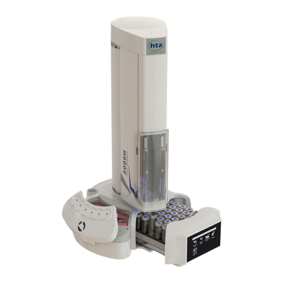
2 Equipment Description 2.1 Parts Definition 2.1.1 HT2000H/HT2000HT Overview 2.1.1.1 HT2000H/HT2000HT Main parts Figure 1: HT2000H/HT2000HT Figure 2: HT2000H/HT2000HT (tray open) top view (tray closed) top view HT2000H_en_n.doc Page 20 of 167... -
Page 21: Ht2100H Overview
SYSTEM INTEGRITY TOOL AREA: only if the System integrity kit option has been supplied (see paragraph 1.7.2 “Options”.) 2.1.1.2 HT2000H/HT2000HT Sample rack HT2000H/HT2000HT standard version uses a 42-position rack. Figure 3: HT2000H/HT2000HT 42 position rack Each vial is identified with two digits (a letter and a number):... - Page 22 On the side of the autosampler there is an incubation oven with 6 heated vial positions. The oven is equipped with a fan, which is used to assist temperature stabilization and the cooling down of the oven. Left configuration Right configuration Figure 4: HT2000H Incubation oven HT2000H_en_n.doc Page 22 of 167...
- Page 23 The oven positions are labelled A-F. In the left figure, the oven is shown open, while in the right figure it is shown closed. 2.1.1.4 HT2000HT Incubation oven On the side of the autosampler there is an incubation oven with 3 heated vial positions. The oven is equipped with a fan, which is used to assist temperature stabilization and the cooling down of the oven.
- Page 24 The oven positions are labelled A-F, but only position B-C-D are used (3 positions). In the left figure, the oven is shown open, while in the right figure it is shown closed. 2.1.1.5 HT2000H /HT2000HT Autosampler base Figure 6: Left location for...
- Page 25 The touch screen display is on the front of the unit. Figure 8: Touch screen display The HT2000H/HT2000HT has a colour LCD display with touch control. The touch screen display can be used to edit the method, sample list or set up as well as running the samples.
- Page 26 DOUBLE FIXED RACK: rack 1A with 8 positions and rack 1B with 6 positions (total 14 sample positions). The 1B rack may be located on the left or right side of the autosampler, depending on how the autosampler is configured. Left/Right side configuration is factory set. TURRET: holds the syringe KEYPAD INCUBATION OVEN/SHAKER: where one sample is heated...
- Page 27 Each vial is identified by a number (from 1 to 14). In block 1A (on the front of the autosampler) vial positions are numbered from 1 to 8, in block 1B (on the left or right side of the autosampler, depending on the factory configuration) vial positions are numbered from 9 to 14.
-
Page 28: Syringe Location
“X” marks the rubber feet, these are important for the installation procedure (see paragraph 3.3.1.1 “Unlock the autosampler from the mounting kit”). 2.1.2.5 HT2100H Control panel: keypad In the front of HT2100H there is the keypad. Figure 14: Keypad (HT2100H) The HT2100H uses a keypad with 4 keys (Move, Start, Wash, Stop) and 4 status LEDs (Err, Ready, Setup, Run). - Page 29 Figure 17: Syringe location The syringe location contains the following parts: 1. Syringe warmer assembly: installed (left), not installed (right) 2. Plunger holder with plunger locker 3. Retaining nuts 4. Needle height regulator (right block) 5. Syringe connection socket 6. Flushing gas inlet 7.
-
Page 30: Connection Panel
“S side” and “B side”. When “S side” is required, please have “S side” facing down; when “B side” is required, please have “B side” facing down. For the HT2000H and HT2100H, side B must be faced downward. Figure 20: “S” side of the plunger locker Figure 21: “B”... - Page 31 Figure 22: Connection panel I/O: ON/OFF Power switch Power cable socket: low voltage power connection (external power supply) RS232C connector: for remote control (serial connection, optional, not present in this picture) RJ45 10/100 auto-sensing connector: for remote control (Ethernet connection, standard) GC connector: for other devices (GC, analyzer..) Service Ethernet reset:...
-
Page 32: Moving Parts
The moving sample tray can be opened/closed (220mm of movement) (in the HT2100H • version it is fixed). The oven cover for HT2000H/HT2000HT (identified as cover) can rotate 35° (open/close • position); The elevator for HT2100H can move vertically by a maximum of about 24mm •... -
Page 33: Tool Kit
Warning If necessary, it is possible to move the turret and needle motors by hand, very carefully, but only when the autosampler is switched off. Rapid movements or movements with the autosampler switched on can damage the autosampler. 2.3 Tool kit The autosampler is provided with a tool kit containing: 1. -
Page 34: Touch Screen Display Description (Ht2000H/Ht2000Ht)
HT2000H/HT2000HT uses touchscreen displays. These can be controlled using your finger tip or with a dedicated stylus. Only use a stylus approved by HTA as using any other stylus (or a pen or pencil), may scratch and damage the touchscreen. -
Page 35: Screen Templates
the enabled buttons use a white font and the disabled buttons use grey font; a button could be disabled because the associated action is not allowed or because other actions must be completed first; when a button has been tapped, the background becomes blue for a while. 2.4.2 Screen templates The screens can be grouped according to type. - Page 36 In this menu, there are up to 6 buttons available. Tap one of the buttons to enter the respective menu/sub menu/function. Special icons: ARROW (see example B, green circle). If more than 6 buttons are available, an ARROW icon is •...
- Page 37 Screen type 4: Figure 32: Screen type 4 This screen type is used for parameter editing. Use the arrows on the right (yellow circles) to change the value of the parameter. Tap “OK” or “SAVE” (not present in this particular example) to confirm the modification, otherwise “CANCEL”...
-
Page 38: Limited Warranty
“CONTINUE” to confirm, • “STOP” or “ABORT” to interrupt the procedure • etc... • Tap the relevant command to perform the task. 2.4.2.6 Screen type 6: Status Information Screen type 6 Figure 35: Screen type 6_example A Figure 36: Screen type 6_example B This screen type describes the status of the autosampler when it is running (injection or wash). -
Page 39: Installation
Warning The autosampler must be located in a place that provides good ventilation. The HT2000H/HT2000HT oven is equipped with a fan, which is used to assist temperature stabilization and the cooling down of the oven. This fan must not be obstructed as it may affect the operation of the unit. -
Page 40: Autosampler Assembly
3.2 Autosampler assembly 1. Open the box. Figure 37: Open the box 2. Remove the protective cushions. Figure 38: Remove the cushions 3. Extract the autosampler from the box and place it on a flat surface in a vertical position. Figure 39: Extract the autosampler from the box HT2000H_en_n.doc Page 44 of 167... - Page 41 Figure 40: Place the autosampler on a flat surface 4. Cut the adhesive tape to open the packaging. Figure 41: Cut the adhesive tape 5. Remove the upper protective cushions. Figure 42: Remove the upper cushions 6. Remove the accessory boxes and extract the included accessories. HT2000H_en_n.doc Page 45 of 167...
- Page 42 8. Check the product sheet to verify that the autosampler configuration (left or right) is consistent with your GC (see paragraphs 2.1.1.5 “HT2000H /HT2000HT Autosampler base” and 2.1.2.4 “HT2100H Autosampler base”). If the configuration of the autosampler is not correct with respect to your GC specification, please contact your local supplier.
-
Page 43: How To Lift And Carry The Autosampler
Before lifting and moving the autosampler it is necessary to remove all of the removable elements: HT2100H: sample vials; • HT2000H/HT2000HT: sample vials and sample rack. • The autosampler must be lifted and carried by hand as shown in the following figure: HT2000H_en_n.doc... -
Page 44: Installation
HT2000H/HT2000HT installation operations should be performed using the touch screen display. HT2100H installation operations should be performed only by using a PC, through the software “HTA Autosampler Manager”; this has the same screens described below for the HT2000H/HT2000HT. 1. Install the autosampler on the mounting plate (see paragraph 3.3.1 “Autosampler installation on the mounting plate”). - Page 45 Please follow these instructions in the following order: 1. Ensure that the autosampler mounting plate is correctly installed on the analyzer and that it allows the correct centering of the autosampler over the injector. The instructions for mounting plate installation are not available in this manual (for this information see the service documentation). The mounting plate is specific for the GC brand and model.
- Page 46 Figure 50: Mounting plate locker opening (example) 3. Place the autosampler over the mounting plate, ensuring that the four rubber feet of the autosampler (indicated with “X” in Figure 6 and Figure 7 ) fit the four plate holes indicated with the letter A in Figure 49: Figure 51: Autosampler mounting over the mounting plate HT2000H_en_n.doc...
- Page 47 4. Fix the autosampler on the plate, closing the locker and pulling it in. Figure 52: Mounting plate locker closing HT2000H_en_n.doc Page 51 of 167...
- Page 48 3.3.1.1 Unlock the autosampler from the mounting kit 1. Open the mounting plate locker, pulling it out using the syringe pointer shown in Figure 24. The opening procedure is shown in the figure below. Figure 53: Mounting plate locker opening 2.
-
Page 49: Safety Lock Setting
3.3.2 Safety Lock setting When shipped the autosampler has the safety lock on, as shown in Figure 59; to work correctly it should be set as shown in Figure 58. Figure 54: Shipping position Figure 55: Moving_1 Figure 56: Moving_2 Figure 57: Moving_3 Figure 58: Moving_4 Figure 59: Operating position... -
Page 50: Electrical Connections
In order to set the regulating lock, please proceed as follows: Warning If you don’t adjust the safety lock, after start up the autosampler will display an error message (see paragraph 8 “Troubleshooting“). For an accurate first installation, do not release the needle guide regulator –... -
Page 51: Purge Line Connections
(low voltage) (see paragraph 2.1.4 “Connection panel“). Connect the external power supply to the mains power. 3. If PC connection is needed (optional for HT2000H/HT2000HT, mandatory for HT2100H): in case of an Ethernet connected autosampler: insert the Ethernet cable provided with •... -
Page 52: Start-Up
During the start up process, the autosampler will proceed to check the incubation oven. For HT2000H/HT2000HT, if the oven is not empty, a screen appears asking if the oven has to be unloaded. If so, a following screen asks where to move the vial(s). -
Page 53: Autosampler Controlled By Lan-Connected Pc
The IT/ network administrator must verify that any software firewall installed on the PC is: disabled; • or enabled, but is not blocking the “HTA Autosampler Manager” application and the ports • 20101 (TCP), 20102 (TCP) and 20201 (UDP); The IT/ network administrator must also be informed about the IP address, because it could be in conflict with the adresses of other devices connected to the LAN or be outside the subnet segment of the LAN. - Page 54 Figure 60: Software versione selection 4) Run the software. 5) (For HTA Autosampler Manager CFR 21 Part 11 version only). At the first access of the software the activation licence is required (click on “Add” from figure “a”, tab “Licences”...
- Page 55 Figure 61: HTA Autosampler Manager CFR 21 Part 11 From the following screen (tab “Instruments” enabled) click on “Add new”: Figure 62: HTA Autosampler Manager screenshot HT2000H_en_n.doc Page 59 of 167...
- Page 56 From the following screen, click on “Next”: Figure 63: HTA Autosampler Manager screenshot Give a “Name” to the instrument in order to identify it more easily, and then click on “Next”: Figure 64: HTA Autosampler Manager screenshot Confirm the instrument is connected by "TCP/IP port" (Default) by pressing on “Next”: Figure 65: HTA Autosampler manager screenshot HT2000H_en_n.doc...
- Page 57 Click on one instrument and then on "Next". If your instrument is not found you can re-try pressing “Refresh”. Figure 66: HTA Autosampler manager screenshot 11) Fill in the form with your data. Click on “Next”: 12) Fill in the form with the analyzer data. Click on “Next”:...
- Page 58 Figure 68: HTA Autosampler Manager screenshot 14) The ending of the activation procedure depends on your type of Internet connection: a) If you have an Internet connection (not via Proxy server) an automatic activation starts. b) If you do not have an internet connection available on the PC you are working with, click on “Activate offline”.
- Page 59 Figure 70: HTA Autosampler Manager screenshot If you already have a “licence key”: select “I have a licence key” and then insert it in the • dedicated field. If you do not have a “licence key” select “I need a licence key” and then “Request •...
- Page 60 Figure 72: HTA Autosampler Manager screenshot 3.5.1.3 IP address/Subnet mask modification If it necessary to modify the IP address/Subnet mask proceed as follows: 1) Connect the autosampler directly to the PC, inserting the Ethernet cable provided with the autosampler in the port indicated with the number 4 in Figure 22 and then into the Ethernet port of the PC (see paragraph 3.3.3 “Electrical connections”);...
-
Page 61: Autosampler Connected Directly To The Pc
3.5.2 Autosampler connected directly to the PC 3.5.2.1 Autosampler connected directly to the PC by the Ethernet port 1) Connect the autosampler directly to the PC, inserting the Ethernet cable provided with the autosampler in the port indicated with the number 4 in Figure 23 and then into the Ethernet port of the PC (see paragraph 3.3.3 “Electrical connections”);... -
Page 62: Accessories Installation
Figure 74: PC connection by RS232 port 3.6 Accessories installation Warning During headspace operation the syringe is cleaned after each injection with inert, clean gas (e.g. N2 or He). Therefore a gas supply line must be available close to the autosampler. Do not use flammable purging gases. -
Page 63: External Pressure Regulator Installation
3.6.1 External pressure regulator installation This optional accessory is used to regulate the pressure of the gas used for the syringe flushing (e.g. Nitrogen). The pressure regulator output must be set at 1 bar maximum (15psi or 100kPa). The external pressure regulator is shown in the figure below: Figure 75: External pressure regulator The pressure regulator must be inserted between the gas source and the gas inlet of the... - Page 64 Figure 76: External pressure regulator connection The other end of the regulator (number 2 in the figure above) must be connected to the gas source. HT2000H_en_n.doc Page 68 of 167...
-
Page 65: Swagelok Adapter Installation
3.6.2 Swagelok Adapter installation Use a Hexagon key (2mm) to unscrew the Rapid fitting terminal (indicated with the letter A in the figure below): Figure 77: Swagelok adapter installation_1 Put the O.R. (indicated with the letter B in the figure below) on the new fitting (indicated with the letter C in the figure below): Figure 78: Swagelok adapter installation_2 Use an open-end wrench (8mm) to screw the fitting and the washer on the female adapter... -
Page 66: System Integrity Tool Installation
Figure 79: Swagelok adapter installation_3 3.6.3 System integrity tool installation Remove the upper part of the Syringe integrity tool (as indicated in the figure below): Figure 80: System integrity tool installation_1 Insert the septum (indicated with the letter A in the figure below) in the lower part of the Syringe integrity tool: HT2000H_en_n.doc Page 70 of 167... - Page 67 Syringe integrity tool to the lower part (indicated with the letter C in the figure below): Figure 82: System integrity tool installation_3 Place System Integrity tool position number 6 Figure 1 for HT2000H/HT2000HT, and Figure 9 for HT2100H. HT2000H_en_n.doc Page 71 of 167...
-
Page 68: Preparing Sample Vial
For sample handling see paragraph 1.1 “Intended use and restrictions”. For HT2000H/HT2000HT: Follow the instruction for sample loading 7.5 “Load and Unload Sample Vial”); •... -
Page 69: Vial Capping (Crimping Cap)
3.7.1 Vial capping (Crimping Cap) Handle unit Adjuster screw Jaws Figure 84: Crimper You must have a crimper available. Fit the septum on the cap, then: Clean the inside surfaces of the crimper jaws. • Place the crimp cap over the top of the vial. •... -
Page 70: Final Installation Operations
Untight cap edge Upward bulge of Deformation of Convex looking Rounded edges/ the crimp cap the crimp cap liner Upward bulge of sides (over- the cap/Liner (overcrimped) crimped) (overcrimped) (overcrimped) (undercrimped) Adjust crimping Adjust crimping Adjust crimping Adjust crimping If the cap is pressure and pressure and height... - Page 71 Syringe purge (see paragraph Syringe purge7.4 “Syringe purge“) • Method and sequence creation and editing (see paragraph 5 “Programming “) • Syringe replacement (see paragraph 4.2.2 “Setup: Syringe warmer assembly installation “) • Front and rear injector alignment (see paragraphs 4.2.1.2 “Alignment: Front Injector and •...
-
Page 72: Set Up Operations
4 Set Up operations The HT2100H set up operations can only be performed using a PC, and the “HTA Autosampler Manager”. HT2000H/HT2000HT set up operations are performed by using the touch screen display, as described in the paragraphs below. Warning... -
Page 73: Setup
Rear Injector Depth: shows the needle insertion depth into the rear injector. This • parameter is shown only if the autosampler is set to work with the rear injector; Rear Injector Insertion Speed: shows the needle insertion speed into the injector. This •... - Page 74 Select “Exit” to exit from this screen and return to the “Setup” screen (see paragraph 4.2 “Setup“). 4.2.1.1 Alignment: Analyzer Default Access sequence: RUN>SETTINGS>SETUP>ALIGNMENT>ANALYZER DEFAULT The first screen (“Setup: Analyzer Brand”) shows a list of analyzer brands. Each brand is associated with a list of models (second screen: “Set up: Analyzer Model”).
- Page 75 System integrity tool in the position indicated with 6 in Figure 1 for HT2000H/HT2000HT and Figure 9 for HT2100H. Tap “Continue” to start, (or “ABORT” to quit). The plunger touch procedure is then run automatically. The vial locator touches the indicated position of the oven cover, the indicated vial in the oven, the indicated vial in the tray, the injector/s and on the System integrity area.
-
Page 76: Setup: Syringe Warmer Assembly Installation
Select “ADD NEW”, to set the number of vial positions, the dimension of the sample vials and the needle draw depth inside the sample vial of the new tray/rack (e.g.: 121-2ml-30mm). To remove a rack, select “REMOVE” then select the tray/rack that you want to remove. A confirmation screen appears “The selected tray has been removed”. - Page 77 Figure 87: Syringe positioning screen 3. When the autosampler is ready, the following screen appears: Figure 88: Syringe remove and installation screen 4. The autosampler should be automatically positioned in a convenient position to allow the syringe warmer assembly installation. If this position is OK, proceed to step 5. 5.
- Page 78 Figure 89: Syringe Install Manual Move screen 6. Follow this procedure: a) Open the syringe location by pushing up the sliding lid. Figure 90: Sliding lid opening HT2000H_en_n.doc Page 82 of 167...
- Page 79 b) Remove the plunger locker by pulling it out using the syringe pointer shown in Figure Figure 91: Plunger locker removing c) Remove the retaining nuts as shown in the figure below. Figure 92: Retaining nuts removing HT2000H_en_n.doc Page 83 of 167...
- Page 80 d) If this is the first installation, proceed directly to point “f)“. e) If this is a syringe replacement, remove the pre-existent syringe warmer assembly with care, as shown in the figure below: Figure 93: Syringe warmer assembly removal Then proceed with the syringe replacement as described in paragraph 9.1.5 “Syringe replacement in the syringe warmer assembly“and proceed to point “f)“.
- Page 81 Mount the syringe warmer assembly with the new syringe installed in the syringe location. Take care to insert the needle inside the vial locator and then plug the syringe warmer assembly into the D-shape connector (number 5 in Figure 17). Insert the plunger in the plunger holder (number 2 in Figure 17).
- Page 82 g) Reposition the retaining nuts and tighten them: Figure 95: Retaining nuts repositioning h) Reinsert the piston locker ensuring that the B side (see Figure 20) is faced downward. Figure 96: Plunger locker positioning HT2000H_en_n.doc Page 86 of 167...
- Page 83 Close the Syringe location by pulling down the lid. Figure 97: Sliding lid closing From the screen reported in Figure 88 or Figure 89 tap “CONTINUE”: then the following screen appears: Figure 98: Syringe volume setting screen k) Set the syringe volume and tap “SAVE” to store the information. HT2000H_en_n.doc Page 87 of 167...
- Page 84 l) Only for HT2000HT. If Syringe Warmer High Temperature Assembly for HT2000HT has been installed you should select as syringe type: “High Temperature”. If Syringe Warmer Assembly for standard version syringe has been installed you should select as syringe type: “Standard”. If the screen for the syringe type selection does not appear contact the Technical Assistance Service.
-
Page 85: Setup: Manual Operations
Plunger, syringe and needle are heated up to 150° C (standard version syringe) or 250° C (HT version syringe installed on HT2000HT). We recommend taking care to prevent injury. To remove the syringe warmer assembly follow the instructions given in paragraph 4.2.2 “Setup: Syringe warmer assembly installation”... - Page 86 (▼) or towards the closed position (▲) (operation not possible for • HT2100H version); open () or close () the oven cover for HT2000H/HT2000HT or the elevator for HT2100H • (closed position is the incubation position);...
- Page 87 Error An error occurred in the movement The status of the oven cover/elevator can be: The oven cover is open/ the Elevator is in the highest position (both not suitable Open for conditioning) The oven cover is moving/ the Elevator is moving Moving The oven cover is closed/ the Elevator is in the lowest position (both suitable for Close...
-
Page 88: Setup: Configuration
High The fan is active (high speed) Very The fan is active (very high speed) High Press “OK” to move the fan at the set speed. This screen also shows: Touch sensor: it is “ON” if the vial locator has detected the presence on an object, or •... - Page 89 Maintenance: displays information and changes settings about preventive maintenance • counters (see paragraph 4.2.4.5 “Setup configuration: Maintenance“); Advanced: edits the advanced parameters of the autosampler (see paragraph 4.2.4.6 “Setup • configuration: Advanced”); Activation: enables the optional features of the autosampler (see paragraph 4.2.4.7 “Setup •...
- Page 90 On: If the power is lost during a run, when the power comes back on, the au- tosampler will restart the injection that it was carrying out at the moment of the Power on- power failure Restart Off: If the power is lost during a run, when the power comes back on, the au- tosampler will return to the home screen (see paragraph 7.1), without completing the run Injection mode: sets the predefined injection mode.
- Page 91 The autosampler The autosampler The autosampler starts sample injects the sample gives the “Start” Injection Synchro preparation in the injector signal to the an- alyzer At the reception of the After ending the When the autosampler touches the injector “Ready” signal from sample preparation the analyzer the autosampler...
- Page 92 Normal: the Maintenance Warning messages will be displayed at the begin- ning of each run, if the set limit is reached (see 4.2.4.5). Maintenance Warning Only at Start up: the Maintenance Warning messages will be displayed only at Start up, if the set limit is reached (see 4.2.4.5). User Interface.
- Page 93 Close: during the injection (for about 1 second) the pins 3 ( and 6 SAMPINS-NO) Start on are closed (short-circuit), while before and after the injection they SAMPINS COM) are open (see paragraph 13.1 GC connector”). Select “Exit” to exit from this screen and return to the “Setup Configuration”” screen (see paragraph 4.2.4 “Setup: Configuration“).
-
Page 94: Setup: Service
(see Figure 1 and Figure 2 for HT2000H and HT2000HT and Figure 9 for HT2100H).The septum of this tool should be replaced periodically (see paragraph 3.6.3 “System integrity tool installation“). This check can verify if it is better to replace the syringe (barrel and plunger). Please note that this check does not replace the necessary periodic validations you have to program for the instrument qualification. -
Page 95: Programming
The methods can be identified by the number or by a name. The name can only be created or edited using a PC (using the “HTA Autosampler Manager” software). Once the names have been created, they will be visible on the touch screen. - Page 96 Injection: see paragraph 5.2.2.5; • Tap “Exit” to exit from the “METHOD X” screen. If one of these parameters has been changed a confirmation screen appears “Modifying Method X”. Tap “SAVE” to save the modifications or “CANCEL” to exit without saving. The display will return to the “RUN: METHODS”...
- Page 97 You can also estimate the Analysis time without making a run. By adding the GC oven program duration and the duration of any post-run programs, you can get close to the true cycle time. Also consider time for data processing. While in most cases data processing is not a problem, a very busy Data system may need extra time between samples.
- Page 98 Oven Temperature: temperature of conditioning of the oven. This value can be between • 40° C and 170° C (for HT2000H)/ 150° C (for HT2100H)/ 300° C (for HT2000HT) or off (inactive conditioning); Incubation: sample incubation time inside the oven;...
-
Page 99: Method Tools
Select “Exit” to exit from this screen and return to the “RUN: METHOD X” screen (see paragraph 5.2.2 “Method X: Setting method parameters”). 5.2.3 Method tools Access sequence: RUN>SETTINGS>METHODS>TOOLS In the “METHOD TOOLS” screen (see paragraph 5.2 “HT2000H/HT2000HT: Methods“), the following options are available: Restore Default: used to load the default settings for a method; •... - Page 100 Value depends on application. Consider boiling point of solvent. 170°C is the maximum temperature that can be set for HT2000H, 150°C is the maximum temperature that can be set for HT2100H, 300°C is the maximum temperature that can be set for HT2000HT.
-
Page 101: Ht2000H/Ht2000Ht: Sequence
Access sequence: RUN>SETTINGS>SEQUENCES>STEP X In the “STEP X” screen (to see how reach this screen see paragraph 5.3 “HT2000H/HT2000HT: Sequence“), the following parameters are available: Tray type: specifies the type of tray to use; • Method: specifies the method to be used;... -
Page 102: Sequence Tools
5.3.3 Sequence tools Access sequence: RUN>SETTINGS>SEQUENCES >TOOLS In the “SEQUENCE TOOLS” screen (to see how to reach this screen, see paragraph 5.3 “HT2000H/HT2000HT: Sequence“), the following options are available: Add New: adds a new sequence step; • Copy as New: creates a new sequence step by copying parameters from an existing one;... -
Page 103: Ht2100H Operations
6 HT2100H operations 6.1 Keys Warning The virtual screen is available only with LAN connection. It is not available with RS232 connection. On the keypad there are 4 keys: Move, Start, Purge, Stop. They have different functions depending on the autosampler status: During operations: MOVE moves the turret from the stand-by position to the injection area (to allow sample •... -
Page 104: Keys Settings
6.1.1 Keys Settings “HTA Autosampler Manager” can define the function of the “PURGE” and “START” keys. In “HTA Autosampler Manager”, select “Auxiliary” tab and then “Key Settings”. If additional help is needed, please refer to “HTA Autosampler Manager” online help. - Page 105 (by PC software). Please connect “HTA Autosampler Manager”, if not connected yet, and act on the “Virtual Screen” tab to exit from the SETUP mode. While in SETUP mode, no operations (start of sample sequence, syringe wash) are allowed.
- Page 106 Meaning A non-blocking error has occurred on Touch Sensor. No motor is selected. Keypad has entered in error modality: by pressing the “MOVE” key you can select a motor • by acting on the “Upward arrow” / “Downward arrow” key you •...
-
Page 107: Ht2000H/Ht2000Ht Operations
7 HT2000H/HT2000HT Operations 7.1 Home screen After the START UP procedure, the autosampler will move the turret to the central position, and the touch screen shows the Home screen. The Home screen is available in two modalities: Standard (see paragraph 7.1.1) and Quick Start (see paragraph 7.1.2 “Home screen: Quick Start User Interface”). -
Page 108: Home Screen: Quick Start User Interface
Tap one of these options to enter the respective sub menu. To move to the Quick Start User Interface, see paragraph 4.2.4.3 “Setup configuration: Run”). 7.1.2 Home screen: Quick Start User Interface Figure 101: Home screen: Quick User Interface From here, it is possible to access the following functions: Start: the autosampler will run all the stored sequence steps (see 5.3.1 “Sequence Menu “) •... -
Page 109: Automatic Run
To set-up or modify a sequence please refer to paragraph 5.3 “HT2000H/HT2000HT: Sequence“. The Last Step must be equal to or greater than the First Step: for example if you set the “First step” as “5”, the last step must be “5” or higher (6-7- 8-9 etc...). -
Page 110: Interrupting An Automatic Run
“MENU” to display method or sequence information; to inject the sample immediately (see paragraph 7.3.2 “Immediate Injection “), to skip the sample injection (see paragraph 7.3.3 “Skip Next Vial option “), or to add or remove samples in the tray/s; “STOP” to end the automatic run (see paragraph 7.3.1 “Interrupting an automatic run). -
Page 111: Syringe Purge
When the tray is open, samples can be loaded or removed. Tap “CLOSE” to close the tray after sample loading/unloading. 7.6 Settings Menu Access sequence: RUN>SETTINGS In this screen the following sub menus are available: Methods: see paragraph 5.2 “HT2000H/HT2000HT: Methods”; • Sequences: see paragraph 5.3 “HT2000H/HT2000HT: Sequence”; • Tray Type: see paragraph 7.6.1 “Change tray/rack type”;... -
Page 112: Change Tray/Rack Type
(if present) the spacers using the suitable tweezers (Spacers kits are sold as options, see paragraph 1.7.2 “Options“). In particular for HT2000H/HT2000HT, the spacers must be installed in the six positions of the oven and for HT2100H, the spacers must be installed in the 14 positions of the sample rack and in the single position of the oven. -
Page 113: Eco Savings
St by oven: sets the oven stand by temperature. This value can be between 40° C • 170° C (for HT2000H)/ 150° C (for HT2100H)/ 300° C (for HT2000HT) or off (inactive conditioning); Or the minimum oven temperature that can be set in your special autosampler version HT2000H_en_n.doc... - Page 114 St by flush: allows the user to open or close the valve that controls the purging gas flow • inside the syringe. Select one of the following values: The valve is open and the gas is flushing inside the syringe The valve is closed.
-
Page 115: Troubleshooting
8 Troubleshooting 8.1 Introduction Warning Troubleshooting must be handled by competent personnel, properly trained with the procedures described in this manual: any missing or different execution of the described procedures can cause damage to the autosampler or to the person working on it. However, in particular, pay attention to the moving parts such as the sledge, syringe, needle etc... -
Page 116: Start Up Errors
8.2 Start up errors 8.2.1 Safety lock error Error message: “Is safety lock in operating position? If NO, switch off and check user manual” Causes: Autosampler has not been moved from the shipping to the operating position, before the • autosampler was switched on (see paragraph 3.3.2 “Safety Lock setting”). -
Page 117: Method Errors
Tap “CONTINUE”. The “Setup: Service” screen appears (see paragraph 4.2.5 “Setup: Service”). Contact your Supplier or the Technical Assistance Centre to solve the problem. 8.2.2.2 Method reading error Error message: “Error during methods reading!" Causes: Autosampler cannot read the parameters of the saved methods. Solution: Tap “CONTINUE”. -
Page 118: Touch Sensor Problems
Solution: Tap “CONTINUE” to edit the method (set “Fill volume” to a value different from zero or set the “Syringe Pre-fill” to NO). 8.4 Touch Sensor problems Error message: “Warning: Check Touch Sensor!” Causes: Touch sensor is not working correctly (normally always on). It is possible that there are mechanical problems. -
Page 119: Obstacle Found
check the vial handlers are not broken; • check the vial, septa and the crimp cap • check if the turret has had an unexplained collision with some object, and if vial handlers or • the vials are dirty. check the turret alignment, if not correct, contact your Supplier or the Technical Assistance •... -
Page 120: Mismatch Errors
8.8 Mismatch errors 8.8.1 Single injection mismatch error If the method parameters conflict with those defined in “setup”, the unit will display an error message. Examples are shown below. Syringe Volume mismatch Error message: “Warning: Run Error Parameters” “Method X: Syringe Volume mismatch” (Where “X”... - Page 121 Solution: Tap “EXIT” and/or: edit the syringe volume set in the method; replace the syringe with one that has the correct capacity; change the syringe volume set during installation if this doesn't match the installed syringe. Then restart the automatic run. 8.8.2.2 Tray Type mismatch Error message: “Warning: Run Error parameters”...
-
Page 122: Missing Errors
Example: only one injector is defined in setup, but “Rear” or “Confirmation” injection mode is used in the sequence step. Solution: Tap “EXIT”. Modify the injection mode in the sequence step (see paragraph 5.3.2 “Setting sequence step parameters“) or the injector type/number in setup setup (see paragraph 4.2.1 “Setup: Alignment “). -
Page 123: Timeout Error
8.10 Timeout error 8.10.1 Peripheral communication timeout Error message: “Time-out communication with peripheral: X” (Where “X” can be Plunger, Needle, Turret, Tray, Shaker etc...). Causes: The communication with the a peripheral fails. Solution: Tap “RETRY” to retry the communication with the peripheral. Tap “DISENGAGE”... -
Page 124: Heating Errors
8.12 Heating errors Error message: “Warning” “Y heater: Code XXX Oven: ZZZ° C (WWW° C) Syringe: KKK° C (JJJ° C) (“Y” can be the Oven or the Syringe according to the heater that has generated the error, “XXX” specifies the error, “ZZZ” is the set temperature for the oven, “WWW is the read temperature for the oven, “KKK”... -
Page 125: Damage To Syringe Needle
The possible causes are: Septum of the System integrity tool must be replaced. • Syringe (barrel and plunger) must be replaced. • Solution: Press RETRY to re-execute the test; • Press CONTINUE, to go on with the run, even if the test has failed. •... -
Page 126: Syringe Inspection
Figure 103: Damage to the syringe needle Verify the specifications of the syringe with that supplied in Appendix B – Consumables. In • particular, check that the needle used has a tip suitable for the septum to pierce. Verify suitable septa were used. •... -
Page 127: Tray Emergency Release
Bend here if necessay Figure 104: Syringe inspection 8.16 Tray emergency release Applies only to HT2000H/HT2000HT. If the tray doesn't open automatically (and samples are inside), please proceed as follows: Switch autosampler OFF; • Wait 30 sec; • Switch it ON again;... - Page 128 Figure 105: Tray opening by hand HT2000H_en_n.doc Page 132 of 167...
-
Page 129: Hta Autosampler Manager" Troubleshooting
The IT/ network administrator must also verify that any software firewall installed on • the PC is: disabled or enabled but it is not blocking the “HTA Autosampler Manager” application and the ports 20101 (TCP), 20102 (TCP) and 20201 (UDP). - Page 130 Figure 107: Set network parameters 3. The IT/ network administrator must check that the suggested network parameters (IP address, Subnet mask, gateway) are actually compatible with your network. 4. If the checking passes, click on “Next” to start the automatic assignment of the new network configuration of your autosampler.
-
Page 131: Analytical Troubleshooting
8.18 Analytical troubleshooting The indications given below are for gas chromatography applications and may not be suitable for other analysis techniques for which this autosampler could be used. When troubleshooting chromatographic symptoms, always remember that the headspace sampler is only part of the system. Evaluate the whole system in order to isolate the problem. Often, issues that appear in the chromatography can be caused by a problem in one or more of the following, in order: The sample;... -
Page 132: Peak Distortion Or Tailing
8.18.2 Peak distortion or tailing Possible causes Solutions Method parameters Check all the method parameters, in particular the sample speed, the pull up strokes (see paragraph 5.2.2.4), the injection speed and the post in- jection dwell (see paragraph 5.2.2.5). Needle penetration speed in GC Check the injection parameters (see paragraph 5.2.2.5). -
Page 133: Faulty Temperature Read-Out
8.18.6 Faulty temperature read-out Possible causes Solutions Probe or sensor of the syringe Contact your service representative. holder temperature are broken Probe or sensor of the oven Contact your service representative. temperature is broken HT2000H_en_n.doc Page 137 of 167... -
Page 134: Maintenance
Be careful to avoid burns. Allow these parts to cool down before handling them. 9.1 Ordinary maintenance The autosampler does not require periodical maintenance other than that described below. 9.1.1 Cleaning of vial rack/tray For HT2000H/HT2000HT: Open the tray (7.5 “Load and Unload Sample Vial”); • Remove the rack from the tray;... -
Page 135: External Cleaning Of Cabinet
Set the oven stand-by temperature to off (see paragraph 7.6.2 “Eco Savings”); • Only for HT2000H/HT2000HT: enter “manual operations” and open the oven cover (see • paragraph 4.2.3 “Setup: Manual operations”); Turn OFF the autosampler and remove the power cable;... -
Page 136: Touch Screen Display Cleaning
Only for HT2000H/HT2000HT enter “manual operations” and close the oven cover (see • paragraph 4.2.3 “Setup: Manual operations”). 9.1.4 Touch screen display cleaning Wet a soft, lint-free or microfibre cloth with distilled water. Wring out as much water as you can. - Page 137 1. Main screws 2. Upper cover 3. Syringe plunger 4. Heating body 5. Insulating gasket 6. Syringe holder 7. Upper spacer 8. Syringe barrel 9. Lower spacers (not used for 5ml syringe) Proceed as described below: 1. Remove the two main screws (number 1 in Figure 109) that secure the upper cover using the supplied allen key (see paragraph 2.3 “Tool kit“).
- Page 138 Figure 110: Removing the upper cover and the syringe plunger 3. Extract the syringe barrel (number 8 in Figure 111), with the insulating gasket (number 5 in Figure 111), the syringe holder (number 6 in Figure 111), the upper spacer (number 7 in Figure 111) and the lower spacers (number 9 in Figure 111, not present in the 5ml syringe) from the heating body (number 4 in Figure 111).
- Page 139 4. The insulating gasket (number 5 in Figure 112), the syringe holder (number 6 in Figure 112), the upper spacer (number 7 in Figure 112) and lower spacers (number 9 in Figure 112, not present in the 5ml syringe) must be extracted from the syringe barrel (number 8 in Figure 112).
- Page 140 7. Also place the insulating gasket (number 5 in Figure 114) inside the heating body (number 4 in Figure 114). Figure 114: Insulating gasket positioning 8. Slide (from the needle side) the upper spacer (number 7 in Figure 115) inside the syringe barrel (number 8 in Figure 115).
- Page 141 Figure 116: Syringe holder positioning 10. Insert the syringe barrel (number 8 in Figure 117), with the upper spacer (number 7 in Figure 117) and the syringe holder (number 6 in Figure 117) mounted on it, in the heating body. The needle has to be inserted through the hole in the bottom of the body. Figure 117: Syringe barrel mounting inside the heating body HT2000H_en_n.doc Page 145 of 167...
- Page 142 11. Only if necessary, also replace the syringe plunger (it is substituted with a lower frequency than the syringe barrel). Remove the plunger (number 3a, 3b and 3c in Figure 118) from the upper cover (number 2 in Figure 118). To separate the plunger from the upper cover unscrew the nut indicated with the number 3a.
- Page 143 3. Extract the syringe barrel (number 8 in Figure 111),), with the insulating gasket (number 5 in Figure 111), the syringe holder (number 6 in Figure 111), the upper spacer (number 7 in Figure 111) and the lower spacers (number 9 in Figure 111) from the heating body (number 4 in Figure 111 4.
- Page 144 9.1.5.3 Standard version syringe: 2.5ml to 1ml syringe replacement Proceed as described below: 14. Remove the two main screws (number 1 in Figure 109) that secure the upper cover using the supplied allen key (see paragraph 2.3 “Tool kit “). 15.
- Page 145 25. Insert the upper cover with the syringe plunger in the syringe barrel. Be sure that the cover fits perfectly with the heating body. Screw in the two main screws that hold the two parts. 26. To replace the syringe warmer assembly in the syringe location, see paragraph 4.2.2 “Setup: Syringe warmer assembly installation”“.
-
Page 146: Septum Of The System Integrity Tool Replacement
Figure 120: HT syringe needle installation 3. To replace the plunger simply lift it up (figure below – a), remove it from the Syringe Warmer High Temperature Assembly for HT2000HT(figure below – b), and replace it (figure below – c). Figure 121: HT syringe plunger replacement 9.1.6 Septum of the System integrity tool replacement HT2000H_en_n.doc... -
Page 147: Preventive Maintenance Pack
The septum of the System integrity tool must be replaced every 30 sample sequences. The Syringe integrity tool location is shown in position 6 of Figure 1 for HT200H/HT2000HT and of Figure 9 for HT2100H. To replace the septum, perform the following operations: remove the System integrity tool from its location;... -
Page 148: Uninstalling And Disposal
2. Remove sample vials and dispose of any residual substances from the instrument in accordance with any applicable safety regulations; 3. For HT2000H/HT2000HT remove the rack(s) from the tray (to open the tray follow the instructions in paragraph 7.5 “Load and Unload Sample Vial”);... -
Page 149: Autosampler Shipping
6. Raise the vial locator; 7. Tighten the left lock; 8. Lift up the sledge manually (see Figure 54); 9. Lower the sliding lid; 10. Switch off the autosampler; 11. Unplug the external power supply from the main power and then remove the power cord from the autosampler;... - Page 150 Figure 123 : Apply the polythene bag Figure 124: Apply the protection belt 5. Apply the lower protective cushions. Figure 125: Position the lower cushions 6. Position the sealed accessory boxes on the autosampler sides. Figure 126: Position the accessory boxes 7.
- Page 151 Figure 127: Position the upper cushions 8. Close the packaging using a suitable adhesive tape. Figure 128: Close the packaging by adhesive tape 9. Put the autosampler in the original box. Figure 129: Put the autosampler in the box HT2000H_en_n.doc Page 155 of 167...
-
Page 152: Autosampler Disposal
10. Insert the protective cushions. Figure 130: Insert the cushions 11. Close and seal the box using suitable adhesive tape. 10.2 Autosampler disposal If the autosampler has to be disposed of, perform the following: Execute the uninstalling procedure described in 10.1 “Autosampler uninstalling”. Place the autosampler and its accessory parts in the original packaging or into another type of packaging suitable for transport. - Page 153 HTA s.r.l., as electronic devices manufacturer, is engaged in the financing and management of electronic equipment's disposal activities. For updated information about the disposal mode and the collection points: contact your sales representative;...
-
Page 154: Appendix A - Glossary
This test is carried out using the system integrity tool (see Figure 1 and Figure 2 for HT2000H/HT2000HT and Figure 9 for HT2100H).The septum of this tool should be replaced periodically (see paragraph 3.6.3 “System integrity tool installation”). - Page 155 Vial leakage check This function can only be enabled by the HTA Autosampler Manager (Setup-Options). If this option is enabled, the pressure inside vials is monitored by a heuristic procedure in order to check against anomalous values that are indicative of a vial leakage problem.
-
Page 156: Appendix B - Consumables
12 Appendix B – Consumables Warning For the sample and reagents handling, see paragraphs 1.1 “Intended use and restrictions” and 1.3 “Warning”. 12.1 Syringes Syringe Type Volume Description Syringe Warmer HTA part Assembly number 3.21.027 1 ml Glass Barrel 3.21.025 1 ml Plunger Standard Version 1.93.841... -
Page 157: Sample Vials
Only for HT2000HT. Standard version syringe installed in the Standard syringe warmer assembly can not work at temperature higher than 150° C. Do not set higher temperatures. The system can be seriously damaged. 12.2 Sample vials HTA Part Number Description Temperature Range (° C) 1.29.949 6ml transparent vials with round end 1.29.941... - Page 158 Warning Correct sample vial dimensions are essential for proper operation. Vials that do not comply with these guidelines should cause autosampler errors. Service calls and repairs found to be due to vials and microvials that do not comply with these guidelines are not covered under warranty or the service contract.
- Page 159 48mm min 38mm ma 2mm min 22.4mm to 23.0mm Figure 132: 10ml sample vial dimensions 12.2.1.3 Specifications for 6ml vials Suitable only for HT2000H/HT2000HT autosampler (not for HT2100H) 10mm min 42.2mm max 40.2mm min 30.2mm max 2mm min 21.5mm to 23mm Figure 133: 6ml sample vial dimensions HT2000H_en_n.doc...
-
Page 160: Cap Specifications
12.2.2 Cap specifications The autosampler uses sample vials with crimp caps. The Minimum diameter of the pierceable area is 9mm. In general, do not use crimp caps more than once for headspace analysis. 12.2.3 Septa specifications Septum material Compatible with Incompatible with Thickness PTFE/silicone... -
Page 161: Appendix C - Connection Panel
13 Appendix C – Connection panel 13.1 GC connector The GC connector is on the connection panel (see paragraph 2.1.4 “Connection panel“). DB15 pin # Function Note +5 Volts Exit = Max. 20 mA FREE3-IN Signal input (true low); Low-level = 0÷0.5 V Hi-level = 4÷12 V SAMPINS-NO Exit = Relay contact (open by default) GCRDY... -
Page 162: Typical Gc Interface
100k Figure 134: GC Connector 13.1.1 Typical GC interface Figure 135: Common interface 13.2 RS232C interface (optional) RS232C Connector, DB9 Connector HT2000H_en_n.doc Page 166 of 167... - Page 163 pin # Function Note N.C. n.c. Transmission Receiving Internally connected with DSR signal DGND Internally connected with DTR signal N.C. HT2000H_en_n.doc Page 167 of 167...
- Page 164 Figure 1: HT2000H/HT2000HT (tray open) top view Figure 2: HT2000H/HT2000HT (tray closed) top view Figure 3: HT2000H/HT2000HT 42 position rack Figure 4: HT2000H Incubation oven Figure 5: HT2000HT Incubation oven Figure 6: Left location for incubation oven (bottom view) Figure 7: Right location for incubation oven (bottom view)
- Page 165 Figure 57: Moving_3 Figure 58: Moving_4 Figure 59: Operating position Figure 60: Software versione selection Figure 61: HTA Autosampler Manager CFR 21 Part 11 Figure 62: HTA Autosampler Manager screenshot Figure 63: HTA Autosampler Manager screenshot Figure 64: HTA Autosampler Manager screenshot...
- Page 166 Figure 99: Screen type 7 Figure 100: Home screen: Standard user Interface Figure 101: Home screen: Quick User Interface Figure 102: HT2000H/HT2000HT rack placing Figure 103: Damage to the syringe needle Figure 104: Syringe inspection Figure 105: Tray opening by hand...
- Page 167 Figure 135: Common interface HT2000H_en_n.doc Page 171 of 167...
Need help?
Do you have a question about the HT2000H and is the answer not in the manual?
Questions and answers