Advertisement
Quick Links
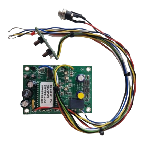
NEDSP1962-KBD User Installation Manual
1. Introduction
The NEDSP1962-KBD amplified DSP noise cancelling module can be retrofitted inside many types of
extension speaker or older style radios and transceivers. It incorporates unique Digital Signal
Processing (DSP) technology which can identify speech from within a noisy signal and can provide up
to 40 dB of noise reduction and 65 dB of tone reduction. The module comes pre-wired and with an
on-board power amplifier enabling it to be easily incorporated into existing equipment. All the
module functions are controlled by the pre-wired keyboard switch assembly. The NEDSP1962-KBD
uses a powerful programmable DSP audio processing chip with DSP noise cancelling technology
inside. This high−performance chip delivers exceptional sound quality and incorporates a full audio
signal chain with 16−bit A/D converters and digital interfaces utilising fully flexible digital processing
architecture. The audio amplifier stage is provided by a Texas Instruments TPA3111D1PWPP Mono
Class-D audio power amplifier chip which is 94% efficient, eliminating the need for heatsinks.
1.1 The NEDSP1962 Module features:
▪
Fully adaptable noise cancellation 9 to 40dB (8 filter levels)
▪
Up to 65% heterodyne tone reduction
▪
Overall Gain control
▪
Input level overload indicator
▪
Easy to install between input and loudspeaker
▪
Frequency Response (50 Hz to 5 kHz)
▪
Up to 7.5 Watts output (4Ω)
▪
Noise Reduction can be preset or remotely set during operation
▪
10 to 18 Volts DC supply range
▪
Adjustable audio indicator "beep" tones
▪
Pcb Mounting Holes
▪
Audio bypassed when power removed
▪
Small Size 70 mm x 50 mm x 12 mm
The NEDSP1962-KBD DSP noise cancelling module is supplied with 1 x 1030-FPL fused DC power
lead, full mounting kit with bhi labels and installation user guide.
1.2 Limitations
This module is designed to pass speech. Other signals such as data, music and morse (CW) will pass
through to some degree depending on the filter level setting, but the integrity of these signals
cannot be guaranteed. This module is designed to be driven from a High-Level signal source capable
of operating into a load of 62Ω impedance.
Important Note: The Audio Output Amplifier is 'Class D' and therefore neither of the output wires
should have any connection to ground, they should only be connected to a speaker or a fully
isolated socket for headphones.
1.3 Module connection and mounting
The module comes pre-wired with a 2.1 mm power socket fitted (centre pin +ve). The "audio in"
and "audio out" connections are pre-wired pairs of wires, ready to be connected into the audio path
1
Advertisement

Related Manuals for BHI NEDSP1962-KBD


Summary of Contents for BHI NEDSP1962-KBD
- Page 1 Audio bypassed when power removed ▪ Small Size 70 mm x 50 mm x 12 mm The NEDSP1962-KBD DSP noise cancelling module is supplied with 1 x 1030-FPL fused DC power lead, full mounting kit with bhi labels and installation user guide. 1.2 Limitations This module is designed to pass speech.
- Page 2 1.6 DSP Noise cancellation The bhi DSP noise cancelling processes the incoming signal and differentiates the speech from the noise. The unwanted noise and interference are attenuated to leave only speech. The following diagrams are taken from actual audio signals and illustrate how the signal the signal looks before and after processing.
- Page 3 2.1 Block Diagram of module Figure 4. NEDSP1962 block diagram...
- Page 4 2. Module Description 2.2 Module Layout The following diagrams show the layout of the NEDSP1962 module Beep Inject jumper JP16 VR3 Beep audio Level adjust Overload LED PL4 External Overload LED Drive Piezo Sounder VR2 Audio output Level adjust Level adjust Figure 5 below.
- Page 5 2.3 Connector and Pin Functions (See pcb layout on page 4 also) PL6 – Power Input Function Connection To Comments + Ve supply 9 Volts to 18 Volts DC -Ve Supply Black PL8 – Audio Input Function Connection To Comments Input Signal Yellow Signal Ground...
-
Page 6: Power On/Off Button
Figure 9. NEDSP1962-KBD Keyboard switch assembly 3.0 Installation 3.1 Installation Overview The NEDSP1962-KBD module is inserted into the path inside the speaker housing/enclosure. 3.2.1 Overview To obtain the best results from this module, it should be set up such that the output level sounds the same whether the module is switched On or Off. - Page 7 3.2.2 Suggested set up procedure: • Ensure that the NEDSP1962-KBD module is un-powered. • Connect/install the module to an appropriate speaker unit. • Connect the speaker to an audio source. • Set the source audio to a typical audio level.
- Page 8 Potentiometer Jumper JP-16 Above picture 3.2.4 Beep Tone level 4.0 Functions 4.1 Keyboard switch assembly The keyboard has 2 push buttons, a Tri-coloured LED and a Red LED. Mode Mode Power On/Off Indicator button button (Tri-colour) Overload/Fault Indicator (Red) M3 Mounting Hole...
- Page 9 4.1.1 Power button The power button toggles the module On and Off. When the power is “Off” the audio bypasses straight through the module directly to the output speaker, so the circuit will behave as if the module isn’t present. Switching the power “On” routes the audio through the module. Note: If the Power is On and the DSP is switched Off, the audio still passes through the DSP processing circuitry, which creates a bandpass filter with Upper and Lower cut-off frequencies of 200 Hz and 5000 Hz.
- Page 10 Holding down the function button down will continuously change the DSP level. When the desired level has been reached, release the button. The module will retain this level until it is changed again. A short press of the Mode button will switch between DSP filter “On” and DSP “Off”...
- Page 11 5.1.0 Specification DC Characteristics Parameter Test Conditions Min. Typ. Max. Units Supply Voltage Quiescent Vs = 10 V to 18 V Current Quiescent current with Vs = 10 V to 18 V DSP On, no load and no signal Current at 400mA Maximum Audio Audio Characteristics...
- Page 12 6.0 Physical Dimensions The following diagrams detail the physical dimensions of the module. All dimensions are 6.1 Main PCB Physical dimensions 6.2 Keyboard hole drilling detail below (drawing not to scale)
- Page 13 7.0 Troubleshooting Clicking sound in a connected speaker or headset. Check the Overload LED. If this is On or flashing for any reason even though no Audio is being passed, this may be indicating a possible speaker fault, the output wires have been shorted or that one of the speaker wires has been grounded.
- Page 14 Ltd 22 Woolven Close, Burgess Hill, West Sussex, RH15 9NR, England Telephone: + 44 (0)1444 870333 Email: sales@bhi-ltd.com Web: www.bhi-ltd.com...
Need help?
Do you have a question about the NEDSP1962-KBD and is the answer not in the manual?
Questions and answers