Advertisement
Quick Links
bhi
NEDSP1901-PCB-MIC User Manual Iss A
Copyright & Disclaimer:
Copyright: This publication, including all photographs and illustrations is protected under
international copyright laws, with all rights reserved. Neither this manual, nor any of the material
within, may be copied or reproduced without the written consent of bhi Ltd.
Disclaimer: The information in this document is subject to change without notice. bhi Ltd. makes no
representations or warranties with respect to the contents hereof and specifically disclaims any
implied warranties of merchantability or fitness for any particular purpose. Furthermore, bhi Ltd.
reserves the right to revise this publication and to make changes from time to time in the content
hereof without obligation of bhi Ltd. to notify any person of such revision or changes.
1. Introduction – The NEDSP1901-PCB module is designed to take line level audio signals and
the NEDSP1901-PCB-MIC version is designed for use with various microphones. They are
separate products and need to be ordered separately, and they are not interchangeable,
although the NEDSP1901-PCB-MIC can also be used with line level audio signals.
Note: Go to page 12 for the specific NEDSP1901-PCB-MIC information
NEDSP1901-PCB Version:
The NEDSP1901-PCB module is an audio DSP noise cancelling module that is used to clean up noisy
speech signals to give improved speech clarity in noisy conditions. The 1901 module is pin for pin
replacement module for the discontinued NEDSP1061-PCB module. It operates with a similar
specification but incorporates the latest bhi DSP noise cancelling technology and maintains virtually
the same physical dimensions as the NEDSP1061-PCB.
1.1 NEDSP 1901 Module Features:
•
Fully adaptive to changing noise environments
•
Input and output level controls
•
Virtually no distortion to speech signals
•
Up to 40 dB noise reduction in 8 selectable levels
•
Audio bandwidth 300Hz to 5KHz
•
Noise Reduction may be preset or remotely set during operation.
•
7 to 18 Volt supply range
•
Approximately 10 dB of signal gain with the ability to drive impedances of less than 1KOhm.
•
Wide range of connection possibilities
•
Mounting holes
Page 1
NEDSP1901-PCB User Manual Iss A
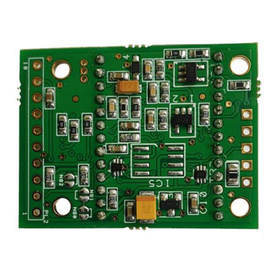
DSP side of PCB
www.bhi-ltd.com
Rear side of PCB
Advertisement

Related Manuals for BHI NEDSP1901-PCB-MIC


Summary of Contents for BHI NEDSP1901-PCB-MIC
- Page 1 Ltd. Disclaimer: The information in this document is subject to change without notice. bhi Ltd. makes no representations or warranties with respect to the contents hereof and specifically disclaims any implied warranties of merchantability or fitness for any particular purpose.
- Page 2 Limitations This module is designed to pass speech. Other signals such as data, music and morse (CW) will, to some degree pass through, but the integrity of these signals cannot be guaranteed. Like the NEDSP1061-PCB module it is designed to be placed in a low-level audio path (up to 1V p-p) only, although there is a level adjustment on the module which will require adjustment.
- Page 3 M2.5 mounting holes to be found at the corners of the board. It’s recommended that Nylon Securing hardware is used to ensure that accidental shorts are avoided due to the fine nature of this PCB. The Audio signal into the module is capacitor coupled to prevent DC offsets being affected. An on-board voltage regulator allows the module to be used with a wide range of input voltages, but to keep the power dissipation (and heat) down, it is advisable to use as low as possible supply voltage.
- Page 4 2.0 Module Description 2.1 Block Diagram The NEDSP 1901 module has the facility to be preset or adjusted during operation. Digital input control the functions. These incorporate internal pull-up resistors so they can be left floating when not in use. The audio signals into and out of the module are capacitor coupled to ensure that no DC levels are pulled down or shorted when the module is used embodied as part of existing equipment.
- Page 5 2.2 Module Layout Figure 3 below shows the board dimension detail as seen from above. The overall thickness of the board is 8.75mm. When considering the installation of this module, at least 9.5 mm height should be provided, which will allow for the clearance of through-hole solder pins. Figure 3.
- Page 6 2.3 Pin Functions The basic operation of the NEDSP pins is described below. More details may be found later in this manual. Pins 1-3 DSP Filter level set -These pins allow remote setting of the noise cancellation level. If these pins are used, then ensure that the appropriate on-board pre-set solder jumpers are removed (JP1 –...
- Page 7 3.0 Installation The NEDSP1901 module is inserted into the path of the noisy audio. Adjusting the Input and Output level controls allows the module to appear transparent to the audio signal level. Figure5. General Audio signal flow with 1901 module installed The NEDSP1901 requires a minimum signal level of 10mV rms or greater for optimum performance.
- Page 8 4.2 Setting different filter levels The levels are set by applying a BCD code to three solder jumpers on the underside of the module. The module can be controlled with a microcontroller. As the DSP employs internal pull-ups, it is not necessary to drive the microcontroller pins high, they can be placed in a high impedance state.
- Page 9 4.5 Noise Reduction On/Off The module has the provision for remotely enabling and disabling the noise reduction, while in operation. The default setting for the module is noise reduction ON. This may be switched by the use of the noise cancellation On/Off pin (PL2 pin 8). To inhibit noise reduction, connect this pin to 0V. To enable the noise reduction, leave the pin unconnected.
- Page 10 The transistors allow interfacing with higher voltages to control the DSP level. As a rough guide the Resistors R1, R3, R5 can be around 10 kOhm. Resistors R2, R4 and R6 could be in the range 2.2 kOhm for control voltages over 10 Volts and 4.7 kOhm for voltages between 5 Volts and 10 Volts.
- Page 11 5.3 Audio Bypass In safety critical applications, a bypass system should be included to maintain communications in the unlikely event of the NEDSP1901 or power failing. The following circuit uses a relay to route the audio signal directly. In the event that the power fails, the Relay will de-energise and connect the Input to...
- Page 12 Using with Microphones The NEDSP1901-PCB-MIC version has as separate plug in DSP module so the following types of microphones or inserts can be used with this version: Magnetic or Dynamic inserts , MEM’s Capsules, Condenser Electret (or just Electret) Capsules...
- Page 13 Biasing an Electret The 1901 board has a 3 to 3.3 Volt supply on pin 2 of PL1. If you have a 2-pin device you will probably need a 2.2 kOhm resistor to feed this voltage to the microphone. The junction of where the resistor joins to the microphone is where the audio is taken off.
- Page 14 DSP input. This is very unlikely to happen even with a MEMs microphone. Setting the gain on the NEDSP1901-PCB-MIC To access the gain links, the plug-in module (IC1) needs to be removed from the socket on the PCB.
- Page 15 Audio Gain settings table Gain Setting (dB) CH1 G0 CH1 G1 CH2 G2 No Jumper No Jumper No Jumper No Jumper Pre -Linked No Jumper No Jumper No Jumper No Jumper Solder Link No Jumper No Jumper Solder Link Solder Link No Jumper No Jumper No Jumper...
- Page 16 Appendix – Reference table showing dBV Vs p-p signal levels and possible gain settings Input (dBV) mV (p-p at Expected 1901 Gain setting Microphone Type 1kOhm) (dB) 5.028 Dynamic/Moving 5.643 Coil 6.331 7.104 7.97 8.943 10.03 11.26 12.63 14.17 15.9 17.84 Electret 20.02...
- Page 17 Contact details: bhi Ltd PO Box 318 Burgess Hill West Sussex RH15 9NR Tel: +44 (0)1444 870333 Email: sales@bhi-ltd.com Web: www.bhi-ltd.com Page 17...
Need help?
Do you have a question about the NEDSP1901-PCB-MIC and is the answer not in the manual?
Questions and answers