Advertisement
Quick Links
5018419
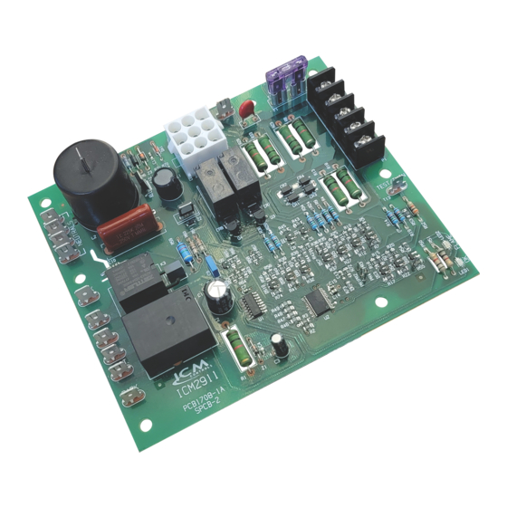
Direct Spark Ignition (DSI) control board
Microprocessor-based
Monitors system timing, trial for ignition, system switches, flame sensing and
lockout
100% lockout safety feature monitors for repeated over-temperature faults or
flame losses and disables the heat operation for safety.
Continuously monitors the gas valve output to verify the gas valve does not
turn on or off incorrectly.
Compatible with LP or Natural Gas
LED indication for status and fault codes to aid in troubleshooting
Twinning feature allows two furnace boards to be controlled with a single
thermostat
• Modine Spark Ignition Control 5H79749
Specifications
Input
• Line Voltage: 120 VAC, 50/60 HZ
• Control Voltage: 18 – 30 VAC, 50/60 HZ
Output
• Heat Blower: 15 FLA/30 LRA @ 120 VAC
• Inducer Fan: ½ HP, (9.8FLA/58.8LRA) @120 VAC
• Gas Valve: 2.3A Pilot Duty @ 24 VAC
Environmental
• Operating Temperature: -40°F to 175°F (-40°C to 80°C), -40°F to 185°F (-40°C to 85°C)
Mechanical
• Dimensions: 6.0"L x 5.0"W x 3.0"D
> > > CAUTION < < <
ELECTRICAL SHOCK HAZARD!
turn off power at the main service panel by removing the fuse or switching
the appropriate circuit breaker to the OFF position. Follow all Local, State and
National Electrical Codes when installing this device.
CAUTION!
Only trained personnel should install or service heating
equipment. When working with heating equipment, be sure to read and
understand all precautions in the documentation, on labels, and on tags that
accompany the equipment. Failure to follow all safety guidelines may result in
damage to equipment, severe personal injury or death.
Electrostatic Discharge (ESD) Precautions
Use caution when installing and servicing the furnace to avoid and control
electrostatic discharge; ESD can impact electronic components. These precautions
must be followed to prevent electrostatic discharge from hand tools and personnel.
Following the precautions will protect the control from ESD by discharging static
electricity buildup to ground.
1. Disconnect all power to the furnace. Do not touch the control or the wiring prior to
discharging your body's electrostatic charge to ground.
2. To ground yourself, touch your hand and tools to a clean, metal (unpainted) furnace
surface near the control board.
Features
Replaces
Before installing this unit,
Direct Spark Ignition (DSI) control board
3. Service the furnace after touching the chassis. Your body will recharge with
static electricity as you shuffle your feet or move around, and you must reground
yourself.
4. Reground yourself if you touch ungrounded items.
5. Before handling a new control, reground yourself, this will protect the control. Store
the used and new controls in separate; containers before touching ungrounded
objects.
6. ESD damage can also be prevented by using an ESD service kit feet or move
around, and you must reground yourself.
Remove Existing Control
CAUTION!
To service control, and prior to disconnection, label all wires.
Failure to do so may result in wiring errors that can cause dangerous operation.
1. Turn thermostat to the OFF position or set it to the lowest possible setting.
2. Turn OFF the electrical supply to furnace.
3. Turn OFF the gas supply to furnace.
CAUTION!
Failure to turn off gas and electric supplies can result in explosion,
fire, death or personal injury.
4. Remove the furnace blower and control access doors.
5. Disconnect the thermostat wires and humidifier wires (if equipped with a humidifier).
6. Disconnect the line voltage, blower, electronic air cleaner wires (if equipped) and
transformer wires.
7. Remove screws and any other fasteners and the old circuit board.
8. Examine the control and the control box for water stains.
9. Make repairs if any sources of water leakage are found. Be sure to check humidifiers,
evaporator coils and vent systems in the area of the control.
Install New Control
1. Ground yourself. When handling the circuit board; hold it by the edges.
2. Fasten the circuit board with the retaining screws.
3. Connect all line voltage, low voltage and accessory wires.
4. Verify the sequence of operation.
Sequence of Operation
When a call for heat is made by connecting the W and R terminals, the control runs through
the following sequence to start the furnace:
• Control board ensures pressure switch is initially open
• The draft inducer motor is energized
• The board confirms draft pressure through closure of the pressure switch
• Inducer performs a 30-second pre-purge delay
• Following the inducer pre-purge delay, the gas valve & spark ignitor energize
• Gas flows into the burners and is lit by the spark igniter
• The flame sensor confirms the presence of flame
• The spark ignitor stops sparking and the gas stays on with the burners lit
• A thirty-second (30S) heat blower pre-heat on delay is enacted to pre- heat the plenum
• Following the 30 second pre-heat delay, the heat blower turns on.
• Loss of the heat call deactivates the gas valve immediately and both the inducer and heat
blowers remain running
• The inducer performs a 60 second post–purge delay upon the loss of the heat call
• The heat blower performs a 90 second post purge following the loss of the heat call
Flame Sense Diagnostics
Flame sensing – The system will use the flame rectification method of flame sensing;
using a remote flame sensing element connected to pin 7 of the P1 connector. The flame
sense circuitry will operate continuously, providing ignition lockout in case flame is sensed
without the gas valve being energized.
Flame sense check – The control expects normal flame to be within 3-5 micro amps and a
sensed flame signal of 1.1 micro amps or below as a weak flame. If flame is sensed during
the 7 second Ignition activation period, the spark ignitor will de-energized after 2 seconds.
Flame circuit is not sensing a flame signal – If the control detects a flame signal when
flame is not expected; the control goes into a 1-hour lockout which engages the inducer
and heat blowers.
Flame loss lockout – If a trial for ignition succeeds and then the flame sensor detects no
flame afterwards, the control will immediately shut off the gas valve and activate the main
blower. If the pressure switch is still closed, the control will attempt another ignition trial
after a 30-second pre-purge delay. If flame is lost 5 times in one call for heat, the control
will go into soft lockout. The inducer will turn off after a 60-second post-purge delay, and the
heat blower will turn off after 90 seconds. The status LED blinks code 7 for the duration of
lockout.
Field Test Mode
Connecting the C terminal to the Test/Twin terminal and disconnecting it in less than
0.9 seconds shall put the control into field test mode. In this mode, pre-purge and heat
blower delay times are reduced. Trial for ignition and inducer post-purge times remains
the same.
Test Mode Delay
Inducer Pre-purge
Trial for Ignition
Blower-On Delay
Inducer Post-purge
Blower-Off Delay
291 1
ICM
Duration (sec)
5
7
10
60
10
LIAF300
Advertisement

Subscribe to Our Youtube Channel
Related Manuals for ICM Controls ICM2911


Summary of Contents for ICM Controls ICM2911
- Page 1 291 1 Direct Spark Ignition (DSI) control board 3. Service the furnace after touching the chassis. Your body will recharge with static electricity as you shuffle your feet or move around, and you must reground yourself. 4. Reground yourself if you touch ungrounded items. 5. Before handling a new control, reground yourself, this will protect the control. Store the used and new controls in separate; containers before touching ungrounded objects. 6. ESD damage can also be prevented by using an ESD service kit feet or move around, and you must reground yourself. Remove Existing Control CAUTION! To service control, and prior to disconnection, label all wires.
- Page 2 Twinning Connection When the twin terminals of 2 controls are wired together, the controls will operate their heat blowers at the same time. Connecting a G call on one control will immediately activate the heat blower on both controls. Removing the G call will immediately deactivate the heat blower on both controls. When the heat blower turns on during the heat cycle of one unit, the heat blower of the second unit turns on at the same time.
Need help?
Do you have a question about the ICM2911 and is the answer not in the manual?
Questions and answers