Table of Contents
Advertisement
Quick Links
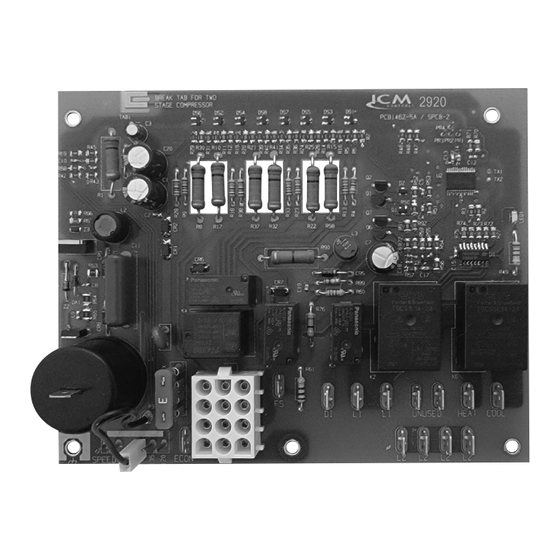
ICM2920
Integrated Furnace Control Board
Installation, Operation & Application Guide
For more information on our complete range of American-made
products – plus wiring diagrams, troubleshooting tips and more,
visit us at www.icmcontrols.com
Introduction
The ICM2920 is a form, fit, and functional replacement for the boards shown
in the cross-reference section of this guide. The ICM2920 is an automated gas
ignition control board which monitors the ignition sequence including the inducer,
pressure switch, spark ignition, gas valve, flame sense, and circulating blower
while maintaining full safety circuit monitoring including the high limit switch, roll
out switch and auxiliary limit switch circuits. Onboard diagnostics will indicate
when a fault condition exists.
Features
• Controls blower motors, gas valve, & spark ignitor in sequence
• Powers a cooling compressor & protects against short-cycling
• Selectable heat blower off-delay time
• Control can be used for 2-stage cooling by removing a tab
• Flash codes from the onboard LED indicate specific problems for easier
troubleshooting
• Repeated ignition failures or flame losses will disable heat operation for
safety
Specifications
Input
• Line voltage: 24 – 230 VAC (RMS)
• Control voltage: 18 – 30 VAC (RMS), 0.15A max.
• Frequency: 50/60Hz
• Fuse rating: 3 A
Output
Relay Contact Ratings:
• Heat/Cool N.O.: 15A FLA, 30A LRA @230 VAC
• Heat/Cool N.C.: 16A FLA, 36A LRA @230 VAC
• Inducer: 4A FLA, 4A LRA @ 230 VAC
• Gas valve: 1.5A @ 24VAC pilot duty
• Compressor contactor: 1.0 A @ 24 VAC
Environmental
• Operating temperature: -40°C to 80C (104°F to 176°F)
• Storage temperature: -40°C to 85C (104°F to 185°F)
• Humidity: 5% - 95% R.H. (non-condensing) at +55˚C
Mechanical
• Dimensions: 6.50" L x 5.15" W x 3.00" D
Replaces
Goodman: PCBAG123, PCBAG123S
Direct Spark Ignition Controls
Mode of Operation
When a call for heat is made by connecting the W and R terminals, the control
runs through the following sequence to start the furnace:
• Ensure pressure switch is initially open
• Turn draft inducer motor on
• Wait for pressure switch to close
• Enact a 15-second pre-purge delay
• Energize gas valve, then spark ignitor
• Prove the Flame through the sensor
• Spark ignitor stops, gas stays on
• Enact a 30-second heat blower on delay
• Turn on the heat blower
When the W call is removed, the cycle ends normally as follows:
• Gas valve deactivates immediately
• Inducer turns off after a 30 second post-purge delay
• Heat blower deactivates after the delay selected by the delay jumper pins, either
150, 135, or 120 seconds
Electrostatic Discharge (ESD) Precautions
Use caution when installing and servicing the furnace
to avoid and control electrostatic discharge; ESD can impact electronic
components. These precautions must be followed to prevent electrostatic
discharge from hand tools and personnel. Following the precautions will
protect the control from ESD by discharging static electricity buildup to
ground.
1. Disconnect all power to the furnace. Do not touch the control or the wiring prior
to discharging your body's electrostatic charge to ground.
2. To ground yourself, touch your hand and tools to a clean, metal (unpainted)
furnace surface near the control board.
3. Service the furnace after touching the chassis. Your body will recharge with
static electricity as you shuffle your feet or move around, and you must
reground yourself.
4. Reground yourself if you touch ungrounded items.
5 Before handling a new control, reground yourself, this will protect the control.
Store the used and new controls in separate; containers before touching
ungrounded objects.
6. ESD damage can also be prevented by using an ESD service kit.
Remove Existing Control
CAUTION!
To service control, and prior to disconnection, label all wires. Failure to do so
may result in wiring errors which can cause dangerous operation.
1. Turn thermostat to OFF position or set it to the lowest possible setting.
2. Turn OFF electrical supply to furnace.
3. Turn OFF gas supply to furnace.
4. Remove furnace blower and control access doors.
5. Remove control box cover.
CAUTION!
Failure to turn off gas and electric supplies can result in explosion,
fire,death, or personal injury.
6. Disconnect thermostat wires and humidifier wires (if equipped with a
humidifier).
7. Disconnect line voltage, blower, electronic air cleaner wires (if equipped), and
transformer wires.
8. Remove wiring harness from circuit board.
9. Remove screws or any other fasteners and old circuit board.
10. Examine control and control box to check for water stains.
11. Make repairs if any sources of water leakage are found. Be sure to check
humidifiers, evaporator coils, and vent systems in the area of the control.
Install New Control
1. Ground yourself properly before installing the new ICM2920 control board.
2. Mount the new control using any screws and fasteners previously removed.
3. Connect all line/low voltage, accessory, thermostat and ground wires.
4. Verify the sequence of operation.
Timing Specification
Heat Operation
Pre-purge
15 seconds
Blower ON
30 seconds
Post-purge
29 seconds
Blower OFF (adjustable)
120/135/150 seconds
Ignition trial
7 seconds
Inter-purge (purge time between trials)
15 seconds
Ignition activation period
5 seconds
Flame establishing period
2 seconds
Flame failure response time
0.8 (max) seconds
Number of trials
3 trials
Hi-Speed Fan
Blower ON
7 seconds
Blower OFF
60 seconds
Cooling Operation
Blower ON
7 seconds
Blower OFF
60 seconds
Compressor anti-short-cycle*
180 seconds
Compressor delay ON make*
60 seconds
* Compressor delay selected with breakaway configuration tab Intact =
3 minutes anti-short-cycle
* Compressor delay selected with breakaway configuration tab broken =
60 seconds delay on make
Blower Timing Select
Blower Off Delay Jumper
When in heat mode, the heat blower turns off 120, 135, or 150 seconds after a W
call ends, depending on the position of the jumper. If the jumper is disconnected,
the control defaults to 150 seconds.
Breakaway Tab For Cooling Anti-Short Cycle Delay
When the breakaway tab is left intact, the control introduces an anti-short-cycle
delay between cooling calls. Hence, once the compressor is deactivated, it will
not activate again for 180 seconds.
Speed Up Jumper
If the speedup pins are jumped at power-on time, the unit will bypass the
compressor anti-short-cycle delay and energize the compressor if a Y call is
in place. If a delay is already in progress when the connection is made, the
board will ignore the remaining time and the compressor contactor activates
immediately. When the tab is removed, the control waits 60 seconds after a Y
call is made before activating the compressor. Any G calls will activate the cool
blower instead of the heat blower.
Lockout
Repeated faults will disable heat operation for safety and the unit will enter
lockout mode. While in lockout, fan & cooling modes operate differently
depending on the cause of the lockout. The control will activate the heat blower &
inducer during lock out. The lockout mode will automatically reset after 1 hour, or
when 24 VAC power is removed for at least 3 seconds.
Fault Code Table For Status LED
Flashes
Fault Condition
Steady ON
Control OK in standby, heat, cooling, or fan modes
Steady OFF
No power, or miswired gas valve
1
Lockout due to flame loss or ignition failure
2
Open pressure switch
3
Pressure switch closed with inducer off
4
Open limit switch
5
Flame detected with gas valve closed
6
Compressor output delayed by anti-short cycle/staging timer
Troubleshooting
Problem
Solution
Thermostat
There are some thermostats which can interfere with the way
interference
the ICM furnace boards sense the call for heat. If you are
having any issues with establishing flame, the first step would
be to remove all the thermostat wires from the board and
temporarily jump R – W to test. If the furnace cycle completes,
remove the jumper, and replace the existing thermostat with a
battery-operated thermostat or a hardwired thermostat which
uses a R & C connection.
Flame Loss
Flame out is considered when flame is lost during heating.
• 5 flame losses in a single heat call will put the control into
a one-hour lockout and the control will flash code 1 on the
status LED for the duration of lockout.
• Removing the W call for more than 3 seconds clears lockout,
and the control will respond to heat and cooling calls again.
If the W call stays in place for 1 hour, lockout will clear
automatically, and the heat cycle will start.
No flame/
• If the flame is not established and proved during the 2
Ignition failure
second initial sequence, there will be two more successive
attempts allowed each having a 15 second inducer purge
between attempts.
• After three successive attempts, if flame is still not proven
there will be a 1 hour lock out before the system will try for
ignition again.
Flame out of
Flame out of sequence represents a scenario when flame is
sequence
sensed while W signal is not present.
• The control goes into a 1-hour lockout when flame is out of
sequence and the indicator LED blinks 5 times. To reset the
lockout, the 24 VAC power must be removed for 3 seconds.
• Inducer and blower motors will be engaged (if not already
running) and keep running for as long as the fault condition
is present.
Pin Socket Pinout
1. 24 VAC HOT from transformer
2. 24 VAC COM/chassis ground
3. Gas valve out
4. Limit switch in
5. Limit switch out
6. Pressure switch out
7. Thermostat G in
8. Pressure switch in
9. Thermostat R out
10. Thermostat W in
11. Thermostat Y in
12. Compressor contactor out
Advertisement
Table of Contents

Related Manuals for ICM Controls ICM2920


Summary of Contents for ICM Controls ICM2920
- Page 1 Use caution when installing and servicing the furnace Flame Loss Flame out is considered when flame is lost during heating. in the cross-reference section of this guide. The ICM2920 is an automated gas to avoid and control electrostatic discharge; ESD can impact electronic • 5 flame losses in a single heat call will put the control into ignition control board which monitors the ignition sequence including the inducer, Cooling Operation components.
- Page 2 Wiring Diagram BREAK TAB FOR TWO STAGE COMPRESSOR Legend Roll Out Switch ICM2920 Limit Switch MADE IN THE USA Auxillary Limit Switch Gas Valve Pressure Switch Compressor Contactor Inducer Motor LED1 Capacitor Economizer ECON Flame Sense Blower Neutral Transformer Primary...
Need help?
Do you have a question about the ICM2920 and is the answer not in the manual?
Questions and answers