Table of Contents
Advertisement
Quick Links
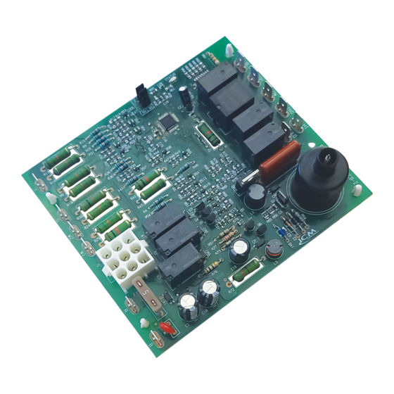
Gas Ignition Replacement Board
Installation, Operation & Application Guide
For more information on our complete range of American-made
products – plus wiring diagrams, troubleshooting tips and more,
visit us at www.icmcontrols.com
• Controls blower motors, gas valve, & spark ignitor in sequence
• Protects against short cycling
• Selectable Heat/Cool blower off-delay time
• Flash codes from the onboard LED indicate specifi c problems for easier troubleshooting
• Repeated ignition failures or fl ame losses will disable heat operation for safety
• 2-stage low heat and high heat
The ICM2915 is a form, fi t, and functional replacements for the boards shown in the cross-reference
section of this guide. The control boards are designed as automated gas ignition controls which monitor
the ignition sequence including the inducer, pressure switch, spark ignition, gas valve, fl ame sense, and
circulating blower while maintaining full safety circuit monitoring including the high limit switch, roll out
switch and auxiliary limit switch circuits. Onboard diagnostics will indicate when a fault condition exists.
In addition, the ICM2915 offers 2-stage low heat and high heat function for better effi ciency.
SPECIFICATIONS
• Line voltage: 240 VAC
• Line frequency: 50/60 Hz
• Control voltage: 18-30 VAC
• Hi-effi ciency blower: 10mA @ 24 VAC
• Inducer blower: 0.7 FLA, 1.5 LRA @ 240 VAC
• Combined gas valve load: 1.5A @ 24 VAC
• Minimum fl ame signal threshold: 0.75 uA
TRANE P/N #: D674713P01
Flashes
Fault Condition
No Power
Steady Off
Normal operation
Steady ON
Normal operation with a heat call in place
Slow Flash
System lock out
2
Pressure switch fault
3
High temperature limit switch open
4
False fl ame sensed
5
Flame rollout switch open
6
W2 called without W1 call from thermostat
7
Low fl ame signal
8
ICM2915
FEATURES
INTRODUCTION
REPLACES
FAULT CODES, STATUS LIGHTS AND TROUBLESHOOTING
Single stage operation
Upon a thermostat call for W1, the single stage heat mode is initiated. The control will verify the initial
state of the pressure switch and other safeties then engage the draft inducer. The control then veri-
fi es the closure of the pressure switch and enters a 20-second pre-purge (15 seconds on high speed
followed by 5 seconds on low speed). After the inducer pre-purge completes, the control energizes the
fi rst stage of the gas valve and initiates spark which ignites the fl ame. Once the fl ame is detected and
verifi ed, a 45 second delay for the indoor blower is initiated. Following the delay, the indoor blower is
energized at low speed. When the W1 call from the thermostat is satisfi ed, the gas valve de-energizes,
fl ame sense is lost, and the control starts a 5 second draft inducer post-purge along with a fi eld selected
60 or 90 second indoor blower post-purge delay. After their delay times expire, the inducer and indoor
blowers will be de-energized.
Second stage operation
When a call for second stage heat (W2) occurs during a fi rst stage heat call (W1), the control changes
the draft inducer speed from low to high speed. Also, the control will switch the fi rst stage gas heat to
the second stage gas heat. Once the call for second stage heat (W2) is satisfi ed, the draft inducer is
switched from high speed to low speed, the gas valve is switched from second stage to fi rst stage, and
the indoor blower speed will switch from high to low within 30s.
First stage and second stage called together at the same time
The control initially processes the call as a single stage heat call. Once fl ame is established, the control
begins to process a second stage heat call operation after 10 minutes.
Note: A call for W2 without a call for W1 will not be recognized.
Cooling mode
Upon a thermostat call for cooling (Y) energized or (Y&G) energized, the control energizes the indoor
blower on high speed. When the thermostat is satisfi ed, the control executes a fi eld selectable 0 or 45
second indoor blower post purge off-delay. When the off-delay ends, the Indoor blower is turned off.
Continuous fan mode
Upon a singular (G) input which indicates a call for continuous indoor blower operation, the control will
energize the indoor blower at the low heat speed.
ELECTRICAL SHOCK HAZARD! Before installing this unit, turn off power at the
main service panel by removing the fuse or switching the appropriate circuit breaker to
the OFF position. Follow all Local, State and National Electrical Codes when installing
this device.
CAUTION! Only trained personnel should install or service heating equipment. When
working with heating equipment, be sure to read and understand all precautions in the
documentation, on labels, and on tags that accompany the equipment. Failure to follow
all safety guidelines may result in damage to equipment, severe personal injury or death.
CAUTION! To service control, and prior to disconnection, label all wires. Failure to do so may
result in wiring errors that can cause dangerous operation.
1. Turn thermostat to the OFF position or set it to the lowest possible setting.
2. Turn OFF the electrical supply to furnace.
3. Turn OFF the gas supply to furnace.
CAUTION! Failure to turn off gas and electric supplies can result in explosion, fi re, death or
personal injury.
4. Remove the furnace blower and control access doors.
5. Disconnect the thermostat wires and humidifi er wires (if equipped with a humidifi er).
6. Disconnect the line voltage, blower, electronic air cleaner wires (if equipped) and transformer wires.
7. Remove screws and any other fasteners and the old circuit board.
8. Examine the control and the control box for water stains.
9. Make repairs if any sources of water leakage are found. Be sure to check humidifi ers, evaporator
coils and vent systems in the area of the control.
1. Ground yourself. When handling the circuit board; hold it by the edges.
2. Fasten the circuit board with the retaining screws.
3. Connect all line voltage, low voltage and accessory wires.
4. Verify the sequence of operation.
Trouble Shooting
Check for 24VAC to the board at terminals R & B on the control board & check power on both the primary and secondary sides
of the stepdown transformer. Check the control board fuse.
Powered up in standby (no call) or powered up with a cool call or fan call in place.
Normal heat call operation.
Check high temperature limit, check fl ame sensor, check gas valve. See lockout conditions in this guide.
Check for obstructed pressure switch tubing or defective pressure switch. Check for oxidation on terminals, broken wires, or
defective inducer motor. Check for proper voltage at the inducer motor input.
Check for blocked airfl ow, blocked ductwork, and dirty fi lter. Check the main blower is working and not bogged down with dirt.
Check or replace high limit switch if defective.
Flame was sensed without gas valve open, or fl ame sensed without a heat call. Check fl ame sensor and all grounds.
Check for blocked exhaust ductwork and check for cracked heat exchanger.
Check to see if W1 & W2 are wired incorrectly.
Check, clean, or replace the fl ame sensor. Check gas valve pressure.
LOCK OUT CONDITION
OPERATION
> > > CAUTION < < <
REMOVE EXISTING CONTROL
INSTALL NEW CONTROL
Advertisement
Table of Contents

Subscribe to Our Youtube Channel
Related Manuals for ICM Controls ICM2915


Summary of Contents for ICM Controls ICM2915
- Page 1 The ICM2915 is a form, fi t, and functional replacements for the boards shown in the cross-reference section of this guide. The control boards are designed as automated gas ignition controls which monitor...
- Page 2 Check the high temperature limit switch for open circuit. Check all safeties. Clean or replace air filter. Check duct work and return air ducts for blockages. continuously WIRING DIAGRAM 0 45 STATUS COOL HEAT ICM2915 LED1 MADE IN THE USA 230 VAC 24 VAC Spark Electrode...
Need help?
Do you have a question about the ICM2915 and is the answer not in the manual?
Questions and answers