Advertisement
Quick Links
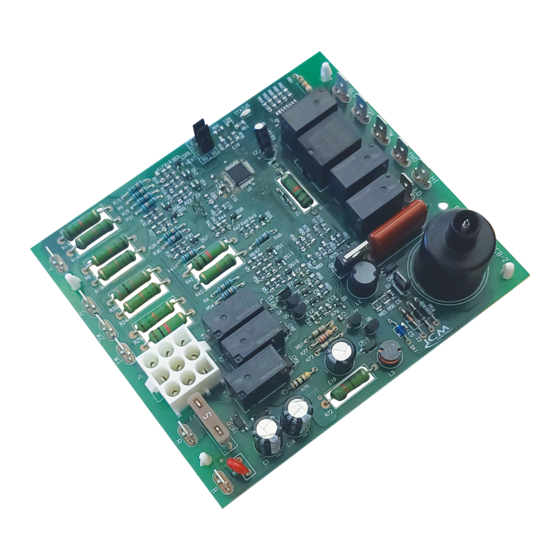
Gas Ignition Replacement Board
Installation, Operation & Application Guide
For more information on our complete range of American-made
products – plus wiring diagrams, troubleshooting tips and more,
visit us at www.icmcontrols.com
• Controls blower motors, gas valve, & spark ignitor in sequence
• Protects against short cycling
• Selectable Heat/Cool blower off-delay time
• Flash codes from the onboard LED indicate specific problems for easier troubleshooting
• Repeated ignition failures or flame losses will disable heat operation for safety
• 2-stage low heat and high heat
INTRODUCTION
The ICM2915 is a form, fit, and functional replacements for the boards shown in the cross-reference
section of this guide. The control boards are designed as automated gas ignition controls which monitor
the ignition sequence including the inducer, pressure switch, spark ignition, gas valve, flame sense, and
circulating blower while maintaining full safety circuit monitoring including the high limit switch, roll out
switch and auxiliary limit switch circuits. Onboard diagnostics will indicate when a fault condition exists.
In addition, the ICM2915 offers 2-stage low heat and high heat function for better efficiency.
SPECIFICATIONS
• Line voltage: 230 VAC
• Line frequency: 50/60 Hz
• Control voltage: 18-30 VAC
• Circulating blower: 4 FLA @ 277 VAC
• Hi-efficiency blower: 10mA @ 24 VAC
• Inducer blower: 0.7 FLA, 1.5 LRA @ 24 VAC
• Combined gas valve load: 1.5A @ 24 VAC
• Minimum flame signal threshold: 0.75 uA
TRANE P/N #: D674713P01
Single stage operation
Upon a thermostat call for W1, the single stage heat mode is initiated. The control will verify the initial
state of the pressure switch and other safeties then engage the draft inducer. The control then veri-
fies the closure of the pressure switch and enters a 20-second pre-purge (15 seconds on high speed
followed by 5 seconds on low speed). After the inducer pre-purge completes, the control energizes the
first stage of the gas valve and initiates spark which ignites the flame. Once the flame is detected and
verified, a 45 second delay for the indoor blower is initiated. Following the delay, the indoor blower is
energized at low speed. When the W1 call from the thermostat is satisfied, the gas valve de-energizes,
flame sense is lost, and the control starts a 5 second draft inducer post-purge along with a field selected
60 or 90 second indoor blower post-purge delay. After their delay times expire, the inducer and indoor
blowers will be de-energized.
Second stage operation
When a call for second stage heat (W2) occurs during a first stage heat call (W1), the control changes
the draft inducer speed from low to high speed. Also, the control will switch the first stage gas heat to
the second stage gas heat. Once the call for second stage heat (W2) is satisfied, the draft inducer is
switched from high speed to low speed, the gas valve is switched from second stage to first stage, and
the indoor blower speed will switch from high to low within 30s.
First stage and second stage called together at the same time
The control initially processes the call as a single stage heat call. Once flame is established, the control
begins to process a second stage heat call operation after 10 minutes.
Note: A call for W2 without a call for W1 will not be recognized.
Cooling mode
Upon a thermostat call for cooling (Y) energized or (Y&G) energized, the control energizes the indoor
blower on high speed. When the thermostat is satisfied, the control executes a field selectable 0 or 45
second indoor blower post purge off-delay. When the off-delay ends, the Indoor blower is turned off.
Continuous fan mode
Upon a singular (G) input which indicates a call for continuous indoor blower operation, the control will
energize the indoor blower at the low heat speed.
ELECTROSTATIC DISCHARGE (ESD) PRECAUTIONS
Use caution when installing and servicing the furnace to avoid and control electrostatic
discharge; ESD can impact electronic components. These precautions must be followed to
prevent electrostatic discharge from hand tools and personnel. Following the precautions will
protect the control from ESD by discharging static electricity buildup to ground.
1. Disconnect all power to the furnace. Do not touch the control or the wiring prior to discharging your
body's electrostatic charge to ground.
2. To ground yourself, touch your hand and tools to a clean, metal (unpainted) furnace surface near
the control board.
3. Service the furnace after touching the chassis. Your body will recharge with static electricity as you
shuffle your feet or move around, and you must reground yourself.
4. Reground yourself if you touch ungrounded items.
5. Before handling a new control, reground yourself, this will protect the control. Store the used and
new controls in separate; containers before touching ungrounded objects.
6. ESD damage can also be prevented by using an ESD service kit.
LIAF315.indd 1
LIAF315.indd 1
ICM2915
FEATURES
REPLACES
OPERATION
> > > CAUTION < < <
ELECTRICAL SHOCK HAZARD! Before installing this unit, turn off power at the
main service panel by removing the fuse or switching the appropriate circuit breaker to
the OFF position. Follow all Local, State and National Electrical Codes when installing
this device.
CAUTION! Only trained personnel should install or service heating equipment. When
working with heating equipment, be sure to read and understand all precautions in the
documentation, on labels, and on tags that accompany the equipment. Failure to follow
all safety guidelines may result in damage to equipment, severe personal injury or death.
REMOVE EXISTING CONTROL
CAUTION! To service control, and prior to disconnection, label all wires. Failure to do so may
result in wiring errors that can cause dangerous operation.
1. Turn thermostat to the OFF position or set it to the lowest possible setting.
2. Turn OFF the electrical supply to furnace.
3. Turn OFF the gas supply to furnace.
CAUTION! Failure to turn off gas and electric supplies can result in explosion, fire, death or
personal injury.
4. Remove the furnace blower and control access doors.
5. Disconnect the thermostat wires and humidifier wires (if equipped with a humidifier).
6. Disconnect the line voltage, blower, electronic air cleaner wires (if equipped) and transformer wires.
7. Remove screws and any other fasteners and the old circuit board.
8. Examine the control and the control box for water stains.
9. Make repairs if any sources of water leakage are found. Be sure to check humidifiers, evaporator
coils and vent systems in the area of the control.
INSTALL NEW CONTROL
1. Ground yourself. When handling the circuit board; hold it by the edges.
2. Fasten the circuit board with the retaining screws.
3. Connect all line voltage, low voltage and accessory wires.
4. Verify the sequence of operation.
Timing: (@ 25 VAC, 60 Hz, 25ºC unless noted)
Function
Time
Heat "ON" delay
45
Cool "ON" delay
1
Flame recognition time
0.8
Flame establishing period
7
Flame failure response time (before 10
2
seconds after trial for ignition period)
Flame failure response time (otherwise) 0.8
Recycle time
20
Lockout time
300
Pre–purge time
20
Retry Time
60
Post–purge time
5
Auto-restart purge time
5
Trial for ignition period
7
Interpurge time
60
Auto restart time
60
Retry
2
Recycle Attempts
4
Heat fan OFF delay
60 or 90 sec., field selectable, default will be 90 sec.
Cool fan OFF delay
0 or 45 sec., field selectable, 45 sec. will be default for HEM,
45 sec. will be default for PSC.
The control will go into a 1-hour soft lockout if the following faults are detected:
• Limit switch open 4 times in one heat call
• Ignition failed (flame not sensed) 3 times in one heat call
• Flame lost after successful ignition 4 times in one heat call
• Gas valve sensed on when it should not be
• Gas valve sensed off when it should be on, 10 times in one heat call
Flame sensed while the gas valve is closed puts the control in lockout state, but lockout clears after the
blower off delay is complete (90 seconds or 60 seconds, depending on jumper selection).
FAULT CODE TABLE
# of Flashes
Error
Steady OFF
No power or board failure
Steady ON
Normal operation with no thermostat call
Slow flash rate
Normal operation with a heat call
2
System lockout
3
Pressure switch fault
4
High temperature limit switch open
5
Flame sensed without gas valve open or flame sensed without W call
6
Flame roll out switch open
7
Thermostat miswired (W1 & W2 reversed)
8
Low flame sense signal
NOTE: At power up, the control will flash the last 4 faults stored in memory within the last 14 days
STATUS LED
Slow Flash: Normal operation with call for heat
Steady Flash: Normal operation without a call for heat
Fault code Retrieval & Clearing
When powering on, the control shall flash the last four error codes that have occurred in the last 14
days. The control will flash the newest error first and oldest error last. The fault memory can be
manually erased by powering on with a G call in place and toggling W 3 times
LOCKOUT
Units
Sec
Sec
Sec
Sec
Sec
Sec
Sec
Sec
Sec
Sec
Sec
Sec
Sec
Sec
Min
Each
Each
4/14/22 11:14 AM
4/14/22 11:14 AM
Advertisement

Related Manuals for ICM Controls ICM2915

Summary of Contents for ICM Controls ICM2915
- Page 1 Function Time Units The ICM2915 is a form, fit, and functional replacements for the boards shown in the cross-reference Heat “ON” delay section of this guide. The control boards are designed as automated gas ignition controls which monitor the ignition sequence including the inducer, pressure switch, spark ignition, gas valve, flame sense, and Cool “ON”...
- Page 2 Check the high temperature limit switch for open circuit. Check all safeties. Clean or replace air filter. Check duct work and return air ducts for blockages. continuously WIRING DIAGRAM 0 45 STATUS COOL ICM2915 HEAT LED1 230 VAC 24 VAC Spark...
Need help?
Do you have a question about the ICM2915 and is the answer not in the manual?
Questions and answers